Method for calibrating driving amount of actuator configured to correct blurring of image taken by camera

Active Publication Date: 2018-06-28
RENESAS ELECTRONICS CORP
View PDF5 Cites 3 Cited by
  • Summary
  • Abstract
  • Description
  • Claims
  • Application Information

AI Technical Summary

Benefits of technology

[0004]In recent years, a camera module is mounted in various devices including a mobile phone terminal, a tablet terminal, and the like. Also, as cameras have been increased in resolution and rendered more multifunctional, the number of components mounte

Problems solved by technology

Other problems and new characteristics will become apparent from the d

Method used


Image

  • Method for calibrating driving amount of actuator configured to correct blurring of image taken by camera
  • Method for calibrating driving amount of actuator configured to correct blurring of image taken by camera
  • Method for calibrating driving amount of actuator configured to correct blurring of image taken by camera

Examples


first embodiment

B. First Embodiment

[0039](b1. Inspection System 200)

[0040]FIG. 2 is a diagram illustrating the configuration example of an inspection system 200 according to the first embodiment. Inspection system 200 includes an information processing terminal 100, a jig 260, a monitor 270, and a test host 280.

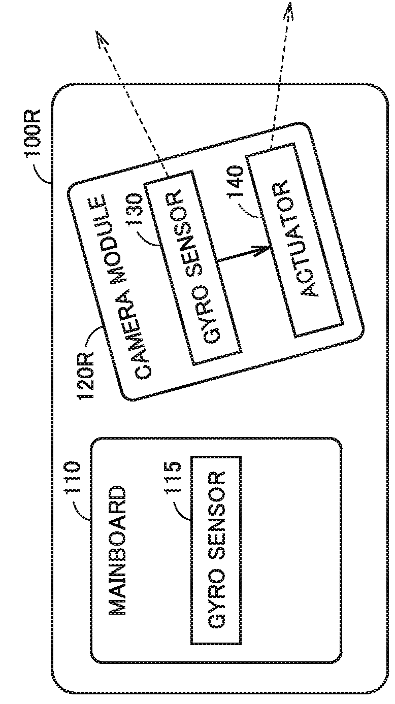
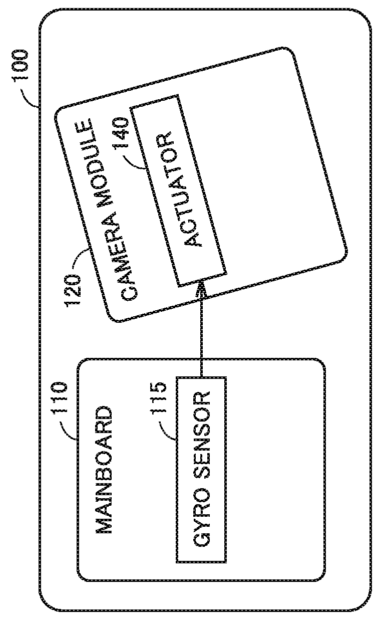
[0041]Information processing terminal 100 includes a mainboard 110 and a camera module 120. Mainboard 110 includes an image memory 205, an image signal processor (ISP) 210, a gyro sensor 115, an application processor (AP) 215, a memory 217, and an interface (I / F) 220. I / F 220 is electrically connected to image memory 205, ISP 210, gyro sensor 115, AP 215, memory 217, and I / F 250 described later.

[0042]Information processing terminal 100 may be provided with a camera (camera module 120), and further provided with a sensor (for example, a gyro sensor) capable of sensing the posture of a terminal and located outside the camera. Information processing terminal 100 may be a smart phone, a tablet, ...

second embodiment

C. Second Embodiment

[0107](c1. Axis Deviation Between Actuator 140 and Image Sensor 225)

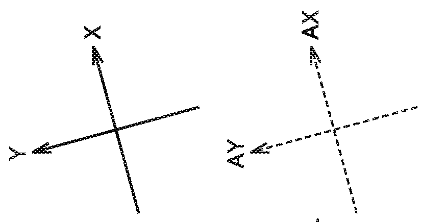
[0108]FIG. 11 is a diagram illustrating deviations between the axes of actuator 140 and the axes of image sensor 225. The axes of image sensor 225 extend in the directions in which a plurality of photoelectric conversion elements forming image sensor 225 are arranged.

[0109]In the first embodiment, it is assumed that the axes (AX, AY) of actuator 140 and the axes (IX, IY) of image sensor 225 coincide with each other. However, these axes may deviate from each other depending on the accuracy of attaching actuator 140 and image sensor 225 during manufacturing of camera module 120.

[0110]In the method of correcting the driving amount of actuator 140 according to the first embodiment, the output from gyro sensor 115 is converted into each axis direction of image sensor 225. Accordingly, by this method, image blurring cannot be accurately corrected if the axes of actuator 140 and the axes of image sensor...

third embodiment

D. Third Embodiment

[0130]In the inspection method according to the above-described embodiment, axis deviation angle θ1 (and θ2) is calculated based on the image obtained by taking an image of the chart to thereby determine, based on this axis deviation angle, the correction coefficient used for correcting the driving amount of actuator 140. In the inspection method according to the third embodiment, information processing terminal 100 is vibrated to thereby determine, based on the output from gyro sensor 115 (vibration information) obtained at the time, the correction coefficient used for correcting the driving amount of actuator 140.

[0131](d1. Inspection System 1400)

[0132]FIG. 14 is a diagram illustrating the configuration example of an inspection system 140 according to the third embodiment. Since the portions designated by the same reference characters in FIG. 2 are the same as those in FIG. 2, the description thereof will not be repeated.

[0133]Inspection system 1400 is different...


PUM


Abstract

A method for calibrating a driving amount of an actuator configured to correct blurring of an image taken by a camera attached to a device includes: taking an image of a mark by a camera to generate a first image, the mark reflecting a predetermined posture of the device; detecting a tilt of the mark in the first image; and based on the tilt of the mark, correcting the driving amount of the actuator that is predetermined according to a sensing result of a sensor for sensing a change in a posture of the device.

Description

[0001]This nonprovisional application is based on Japanese Patent Application No. 2016-253390 filed on Dec. 27, 2016 with the Japan Patent Office, the entire contents of which are hereby incorporated by reference.BACKGROUND OF THE INVENTIONField of the Invention[0002]The present disclosure relates to a technique for correcting the driving amount of an actuator for correcting blurring of an image taken by a camera.Description of the Background Art[0003]Conventionally, various techniques for correcting blurring of an image taken by a camera have been proposed. For example, Japanese Patent Laying-Open No. 2016-173517 discloses an image blurring correction device configured to “temperature-correct, among the motor control amounts applied during correction of image blurring, (i) the movement-control amount with the first correction coefficient, and (ii) the hold-control amount used for holding a blurring correction mechanism 110 in the center position with the second correction coefficie...

Claims


Application Information

Patent Timeline
IPC IPC(8): H04N5/232G02B23/24
CPCH04N5/23267H04N5/23212H04N5/23287G02B23/24G03B5/00H04N23/67H04N23/68H04N23/6812G02B13/001G02B27/646H04N17/002H04N23/57H04N23/687H04N23/6811H04N23/685G01C25/005H04N23/683
Inventor MURAKAMI, HIROSHIMURAKAMI, MITSUMASA
Owner RENESAS ELECTRONICS CORP
Why Eureka
Try Eureka