Internal edge verification

Active Publication Date: 2020-03-12
SEIKO EPSON CORP
View PDF0 Cites 4 Cited by
  • Summary
  • Abstract
  • Description
  • Claims
  • Application Information

AI Technical Summary

Benefits of technology

[0010]In some embodiments, the first features are internal edges that are other than a contour of the object in the first image frame. In some embodiments, the coordinate points of the first and second features include two-dimensional and three-dimensional points. In some embodiments, the neighboring view is within 10° of the view. In some embodiments, the method further includes: determining if an object size within the first image frame is below a threshold size, and when the object size is below the threshold size, increasing a resolution of the object in the second image frame. In some embodiments, the method further includes, before storing the second template data, removing a coordinate point in the second template data that is within a predetermined distance to another coordinate point in the second template data.
[0011]In order to achieve these benefits, embodiments of the disclosure further include a non-transitory computer readable medium that embodies instructions that cause on or more processors to perform

Problems solved by technology

In AR and VR, one problem is that of tracking the 3D pose of the object with respect to the camera so that various augmented or virtual reality elements can be anchored to the object.
One problem that arises in object tracking is attempting to detect object poses for obje

Method used


Image

  • Internal edge verification
  • Internal edge verification
  • Internal edge verification

Examples


Embodiment Construction

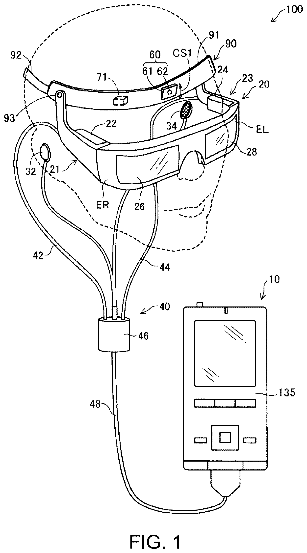
[0026]FIG. 1 shows a schematic configuration of an HMD 100. The HMD 100 is a head mounted display device (a head mounted display). The HMD 100 is an optical transmission type. That is, the HMD 100 can cause a user to sense a virtual image and, at the same time, cause the user to directly visually recognize an outside scene.

[0027]The HMD 100 includes a wearing belt 90 wearable on the head of the user, a display section 20 that displays an image, and a control section 10 that controls the display section 20. The display section 20 causes the user to sense a virtual image in a state in which the display section 20 is worn on the head of the user. The display section 20 causing the user to sense the virtual image is referred to as “display AR” as well. The virtual image sensed by the user is referred to as AR image as well.

[0028]The wearing belt 90 includes a wearing base section 91 made of resin, a belt 92 made of cloth coupled to the wearing base section 91, a camera 60, and an IMU (I...


PUM


Abstract

A method for one or more processors to implement includes acquiring a synthetic image of an object from a second orientation different from a first orientation, using a three-dimensional model. The method further includes identifying, in the synthetic image, second edge points that are located on an edge of the object that is not a perimeter. The method further includes identifying matched edge points, which are first edge points and second edge points at substantially a same location on the object. The method further includes storing the matched edged points in a memory that can be accessed by an object-tracking device, so that the object-tracking device can identify the object in a real environment by identifying the matched edge points in images of the object.

Description

BACKGROUND1. Technical Field[0001]The disclosure relates generally to the field of object detection and pose estimation in image data streams, and more specifically to augmented reality system including low feature object detection and pose estimation in image data streams.2. Related Art[0002]Augmented Reality (AR) has become increasingly common with the advancement of computer technology. A general definition of AR is capturing a real-world scene and adding artificial (virtual) elements using software. This can enhance a user's perception of the real world or provide entertainment to the user.[0003]Object tracking is important in many AR implementations. This means that a real-world object is “followed” by an artificial object, such as computer-graphics enhancements or an information bubble (as perceived by the user). In other words, if the real-world object moves or the user's view moves relative to the real-world object, the artificial object will remain in the same location rela...

Claims


Application Information

Patent Timeline
IPC IPC(8): G02B27/01G06T7/73G06T7/20G06T7/13G06T19/00
CPCG06T7/20G06T7/75G02B27/0172G06T7/13G06T19/006G02B2027/0138G02B2027/0178G02B27/017G02B2027/014G02B2027/0187G06T7/251G06T2207/30208G06T2207/30244
Inventor BRUSNITSYN, MIKHAIL
Owner SEIKO EPSON CORP
Why Eureka
Try Eureka