Female contact

Inactive Publication Date: 2005-07-28
JST MFG CO LTD
View PDF11 Cites 3 Cited by
  • Summary
  • Abstract
  • Description
  • Claims
  • Application Information

AI Technical Summary

Benefits of technology

[0019] With the foregoing construction, the first protrusion of the flat spring and the first hole of the socket are engaged with each other, thereby latching the flat spring to the socket. Thus, the flat spring is, via its first protrusion, latched in the vicinity of the male-contact inlet of the socke

Problems solved by technology

This may cause deformation of the one end of the flat spring 520 which is not latched to the socket 510, and thus elasticity of the flat spring 520 can often be deteriorated.
As a result, a male contact accommodated in the socket 510 c

Method used


Image

  • Female contact
  • Female contact
  • Female contact

Examples


Example

[0034] In the following, a certain preferred embodiment of the present invention will be described in conjunction with the accompanying drawings.

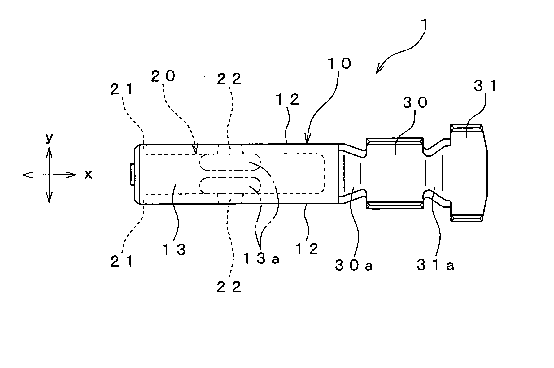
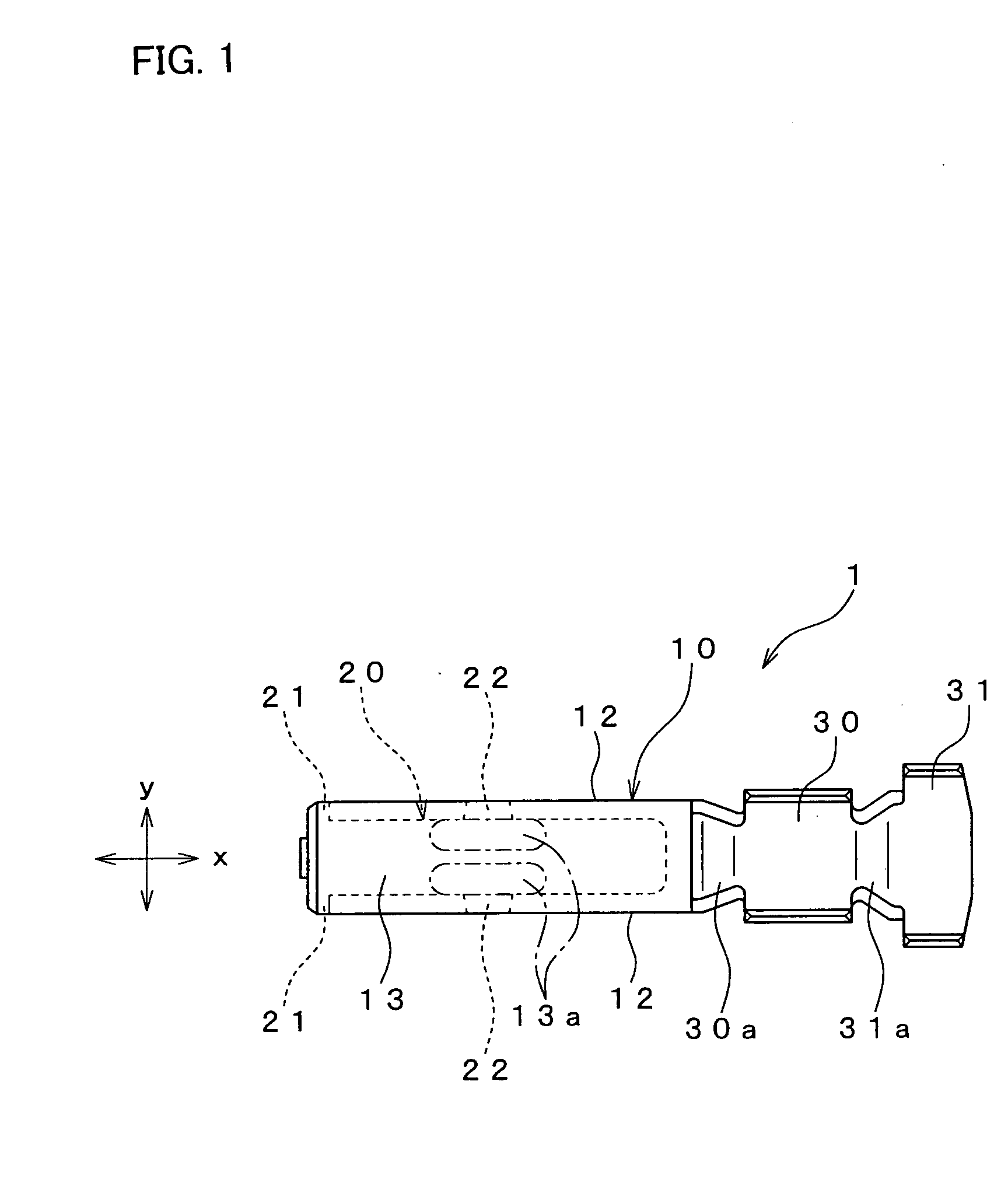
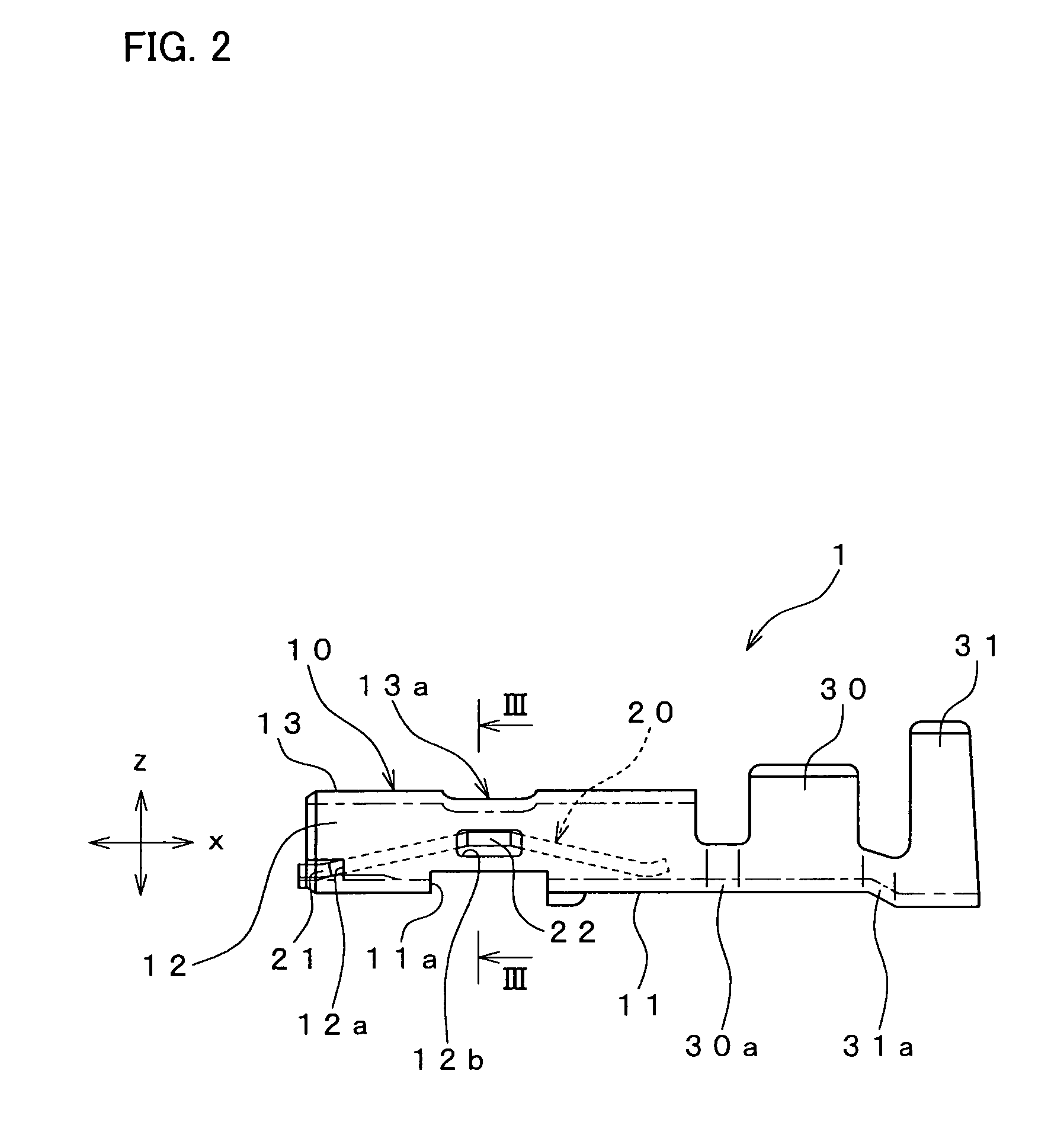
[0035] First, a female contact according to an embodiment of the present invention will be described with reference to FIGS. 1, 2, 3, and 4. In FIGS. 1 and 2, arrows x, y, and z which are perpendicular to one another stand respectively for lengthwise, widthwise, and vertical directions of a female contact 1 of the embodiment. The direction x follows a direction in which a male contact is inserted into or pulled out of the female contact 1, and the direction z follows a direction in which a later-described flat spring exerts its elastic force.

[0036] The female contact 1 comprises, from left to right in FIGS. 1 and 2, a socket 10, a conductor crimper 30, and an insulator crimper 31. The socket 10 has a substantially rectangular-cylindrical shape that is elongated in the direction x. The conductor crimper 30 is connected, via a connecting po...


PUM


Abstract

A female contact comprises a tube-shaped socket having a male-contact accommodation space, and a flat spring held in the socket so as to apply elastic force to a male contact. A notch is formed at a male-contact inlet of the socket. A hook formed at one end of the flat spring is engaged with the notch, so that the flat spring is latched at the male-contact inlet.

Description

BACKGROUND OF THE INVENTION [0001] 1. Field of the Invention [0002] The present invention relates to a female contact that has a socket for removably accommodating a male contact such as plug or pin-type terminal so that an electrical contact occurs therebetween, and more specifically relates to a female contact that has a flat spring held in its socket. [0003] 2. Description of Related Art [0004] In a known technique (Japanese Patent Unexamined Publication No. 55-111082), a female contact has a socket for accommodating a male contact such as plug or pin-type terminal. The female contact includes, in its socket, a flat spring whose elastic force is exerted on a male contact accommodated in the socket, thereby keeping good electrical contact with the male contact. [0005] According to the foregoing technique, a female contact 501 (see FIG. 13) is manufactured through a process such as bending and cutting a metal flat plate 601 (see FIG. 10). In FIGS. 10 to 12, base elements that are i...

Claims


Application Information

Patent Timeline
IPC IPC(8): H01R13/11H01R13/187H01R13/40H01R13/428H01R43/16
CPCH01R13/428H01R13/113H01R43/16H01R13/40
Inventor SAWADA, TAKAOIKUTA, KEICHIROWADA, MASATO
Owner JST MFG CO LTD
Why Eureka
Try Eureka