Engine fuel injection apparatus

a technology for engine fuel injection and fuel injection valves, which is applied in the direction of machines/engines, electric control, combustion air/fuel air treatment, etc., can solve the problems of difficult to improve and achieve the effect of improving the maintenance and inspection of the fuel injection valv

Active Publication Date: 2005-09-22
HONDA MOTOR CO LTD
View PDF7 Cites 9 Cited by
  • Summary
  • Abstract
  • Description
  • Claims
  • Application Information

AI Technical Summary

Benefits of technology

[0007] Accordingly, an object of the present invention is to provide a technology that can improve the maintenance and

Problems solved by technology

Accordingly, it is difficult to improve the maintenance and inspection of the fuel injection

Method used


Image

  • Engine fuel injection apparatus
  • Engine fuel injection apparatus
  • Engine fuel injection apparatus

Examples


Embodiment Construction

[0034] Referring to attached drawings, an embodiment of the present invention will be described below. The terms “front”, “rear”, “left”, “right”, “up” and “down” refer to directions as viewed from the perspective of a driver. The drawings should be viewed so that the reference numerals are oriented in an upright position.

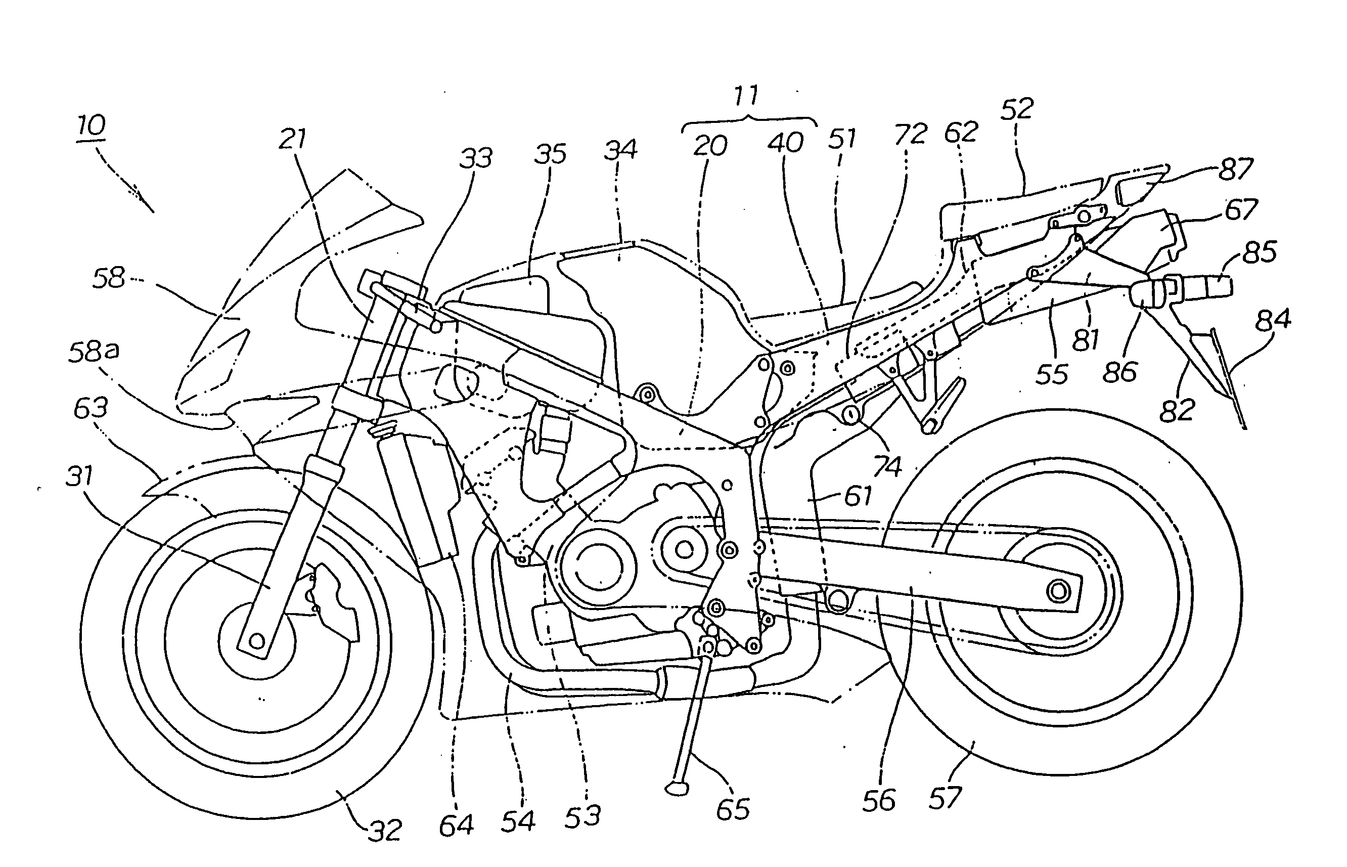
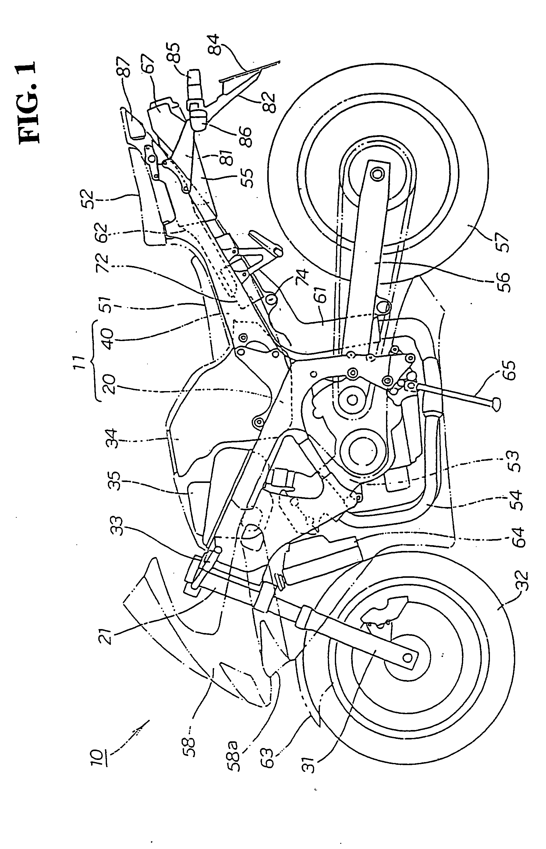
[0035]FIG. 1 is a left side view of a motorcycle according to the present invention. A motorcycle 10 includes a cradle type vehicle body frame 20. A front fork 31 is mounted to a head pipe 21 of the vehicle body frame 20. A front wheel 32 is attached to the front fork 31. A handle or handle bar 33 is connected to the front fork 31. A fuel tank 34 and an air chamber 35 are mounted on the vehicle body frame 20. A seat rail 40 extends rearward from the vehicle body frame 20. A front seat 51 and a rear seat 52 are mounted on the seat rail 40. A four-cycle engine 53 is disposed in a cradle space of the vehicle body frame 20. A muffler 55 is connected to an exhaust port...


PUM


Abstract

To improve the maintenance and inspection of a fuel injection valve, as well working of the fuel piping and wiring to the fuel injection valve. An engine fuel injection apparatus includes an air chamber provided on an upstream end of an air intake passage of an engine. A first fuel injection valve for injecting fuel toward the upstream end of the air intake passage is provided on a wall of the air chamber facing a wall connected to the upstream end of the air intake passage. The fuel piping and wiring to the first fuel injection valve is located outside of the air chamber. The air chamber also serves as an air cleaner case provided with a filter element therein.

Description

CROSS-REFERENCES TO RELATED APPLICATIONS [0001] This application is a Continuation of co-pending application Ser. No. 10 / 649,836, filed on Aug. 28, 2003, the entire contents of which are hereby incorporated by reference and for which priority is claimed under 35 U.S.C. § 120. This nonprovisional application also claims priority under 35 U.S.C. § 119(a) on patent application No. 2002-266140 filed in Japan on Sep. 11, 2002, the entirety of which is herein incorporated by reference.BACKGROUND OF THE INVENTION [0002] 1. Field of the Invention [0003] The present invention relates to an improvement of an engine fuel injection apparatus. [0004] 2. Description of Background Art [0005] Japanese Patent Application Laid-open No. 2000-97132 (Pages 2-3, FIGS. 1-2) discloses an engine fuel injection apparatus in the background art, which includes an air chamber provided on an upstream end of an air intake passage of an engine. The air chamber is a two-half chamber including a lower chamber and an...

Claims


Application Information

Patent Timeline
IPC IPC(8): F02M35/024F02B61/02F02M35/10F02M35/16F02M61/14F02M69/00F02M69/04
CPCF02B61/02F02M35/02F02M35/10039F02M35/10052F02M69/043F02M35/10216F02M35/10301F02M35/162F02M61/145F02M35/10177
Inventor KURAYOSHI, YOSHIYUKIAKAGI, TAKASHIYUHARA, TOMOMIHIRAO, NAOHISA
Owner HONDA MOTOR CO LTD
Why Eureka
Try Eureka