Method of adjusting monitor axis

Inactive Publication Date: 2005-10-06
ORMON CORP
View PDF1 Cites 50 Cited by
  • Summary
  • Abstract
  • Description
  • Claims
  • Application Information

AI Technical Summary

Benefits of technology

[0024] If a target according to these examples is used, a waveform of W-form or inverted W-form can be easily obtained for received

Problems solved by technology

For this reason, there was a possibility with conventional devices that there may result a significant distance between a monitored position and an actual position near the edge of a detection area (far from the center axis) even after an axial adjustment and that no sufficiently accurate measurement could be made.
If the monitoring device is of a fusion type, employing a plurality of sensors (such as a radar and a camera), however, the merits of the fusion type cannot be fully utilized without taking into consideration a proper correlation between the results of measurement by the sensors.
The conventional methods of axial adjustment had problems in the case of a fusion type employing both a radar and a camera because different targets had to be used for axially adjusting the radar and the camera independently of each other.
Firstly, if the conventional method of axial adjustment is applied to t

Method used


Image

  • Method of adjusting monitor axis
  • Method of adjusting monitor axis
  • Method of adjusting monitor axis

Examples


Embodiment Construction

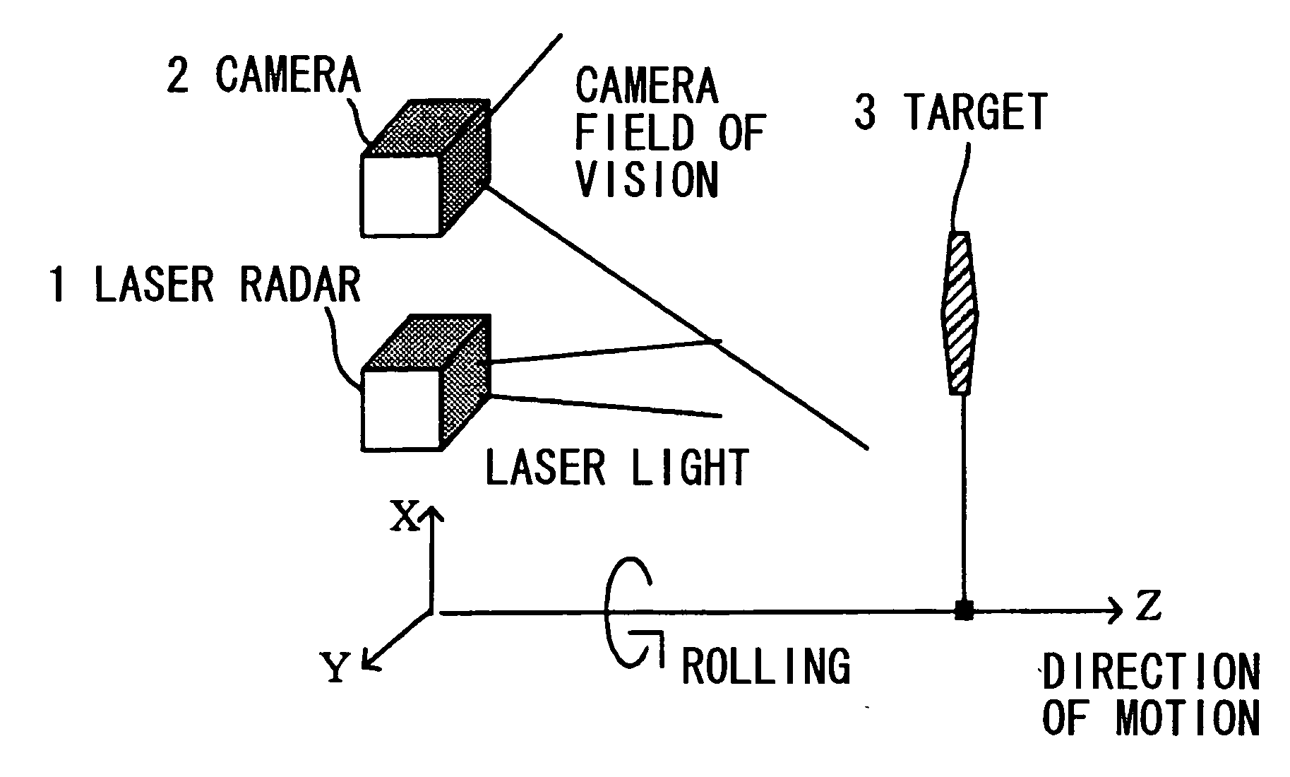
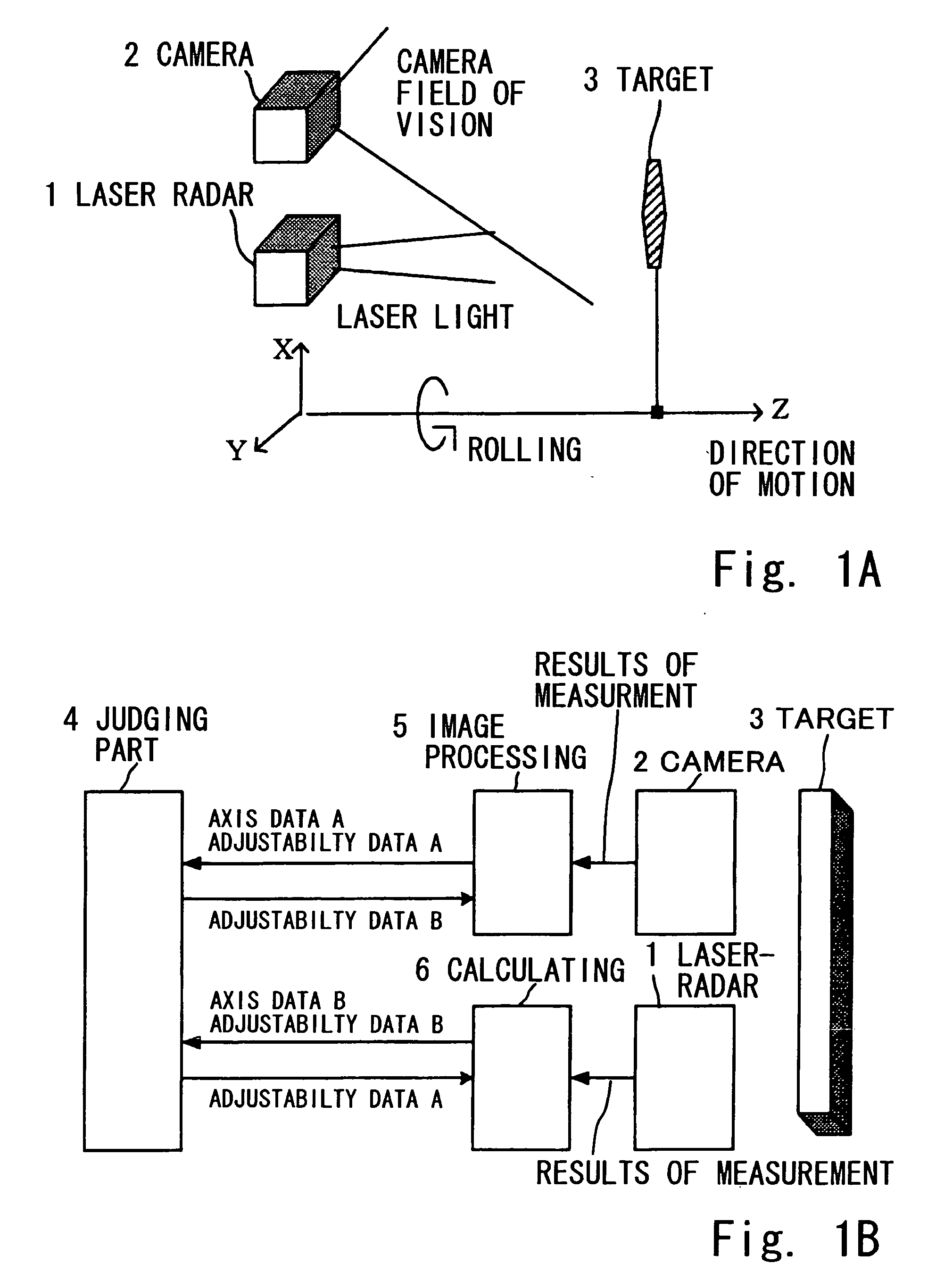
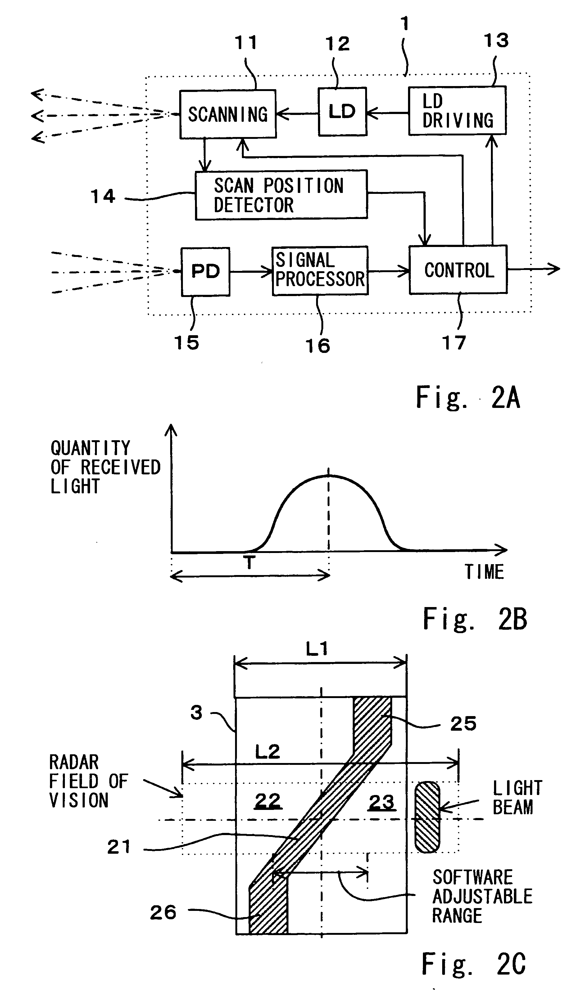
[0044] The invention is described next by way of an example with reference to FIGS. 1A, 1B, 2A, 2B and 2C. FIG. 1A shows the main structure of an equipment and FIG. 1B is a block diagram for explaining the control system of a monitor. FIG. 2A is a block diagram for showing the structure of a laser radar. FIG. 2B is a drawing for showing the principle of measurement by it, and FIG. 2C is a front view of a target used for adjustment.

[0045] In FIG. 1A, numeral 1 indicates a laser radar (hereinafter simply referred to as a radar) and numeral 2 indicates a camera set on the same vehicle as the radar 1. The radar 1 in this example is a two-dimensional scan laser radar capable of scanning in both the horizontal left-right direction and in the vertical up-down direction. Numeral 3 indicates a target used for adjustment. In this example, the left-right direction as seen from the radar 1 and the camera 2 is the standard direction of the scan and the vertical direction is sometimes referred t...


PUM


Abstract

The invention relates to a method of adjusting a monitor having a radar and a camera and correcting the positions and orientations of their detection areas based on intensity of reflected light from a target object. A single target having a specified pattern of bright and dark areas in placed in front of the monitor in the detection areas of the radar and the camera. The detection area of the radar is adjusted first based on measurements taken of the target by the radar and thereafter axial displacement of the detection area of the camera is determined a coordinate conversion parameter is obtained based on an image of the target taken by the camera.

Description

[0001] Priority is claimed on Japanese Patent Application 2004-110589 filed Apr. 2, 2004. BACKGROUND OF THE INVENTION [0002] This invention relates to monitors such as radars adapted to be carried on a vehicle for obtaining position data of a front-going vehicle by making use of wave motion such as radar light and more particularly to the technology of adjusting the position and orientation of the detection area of such a monitor or its optical axis herein referred to as the monitor axis. [0003] Apparatus of the kind carried on a vehicle for monitoring front-going vehicles and obstacles or for cruise control are widely being developed and the kinds with a radar using electromagnetic waves or a laser are generally known. They are devices for transmitting electromagnetic waves or laser light to an object of detection within a specified detection area and measuring the distance to a target object from the delay of a reflected signal. [0004] In the case of a laser radar, for example, a ...

Claims


Application Information

Patent Timeline
IPC IPC(8): G01S7/40G01S7/497G01S17/86G01S17/931G05D1/02G06K9/46
CPCG01S7/4026G01S7/4972G01S2007/403G01S17/936G01S2007/4034G01S17/023G01S17/86G01S17/931G01S7/4034G01S7/403
Inventor HORIBE, KOJIMATSUURA, YOSHIO
Owner ORMON CORP
Why Eureka
Try Eureka