Method and apparatus for attaching power line communications to customer premises

a technology for power line communications and customer premises, applied in powerline communications applications, data switching networks, instruments, etc., can solve problems such as 3-phase electrical power/wiring, and achieve the effect of significant operating convenience and little (or no) additional cos

Inactive Publication Date: 2005-11-17
TELKONET COMM INC
View PDF96 Cites 15 Cited by
  • Summary
  • Abstract
  • Description
  • Claims
  • Application Information

AI Technical Summary

Benefits of technology

[0004] There are significant practical advantages offered by PLC technology—namely that electrical wiring, of necessity, must be installed and that data connectivity can therefore be immediately added at little (or no) additional cost, particularly in existing buildings. Similarly, electrical outlets are ubiquitous within modern buildings and significant operating convenience is realized when data is simultaneously available at every outlet.
[0005] Another advantage of PLC technology is that the range that can be achieved is significantly greater than wireless methods, particularly in commercial buildings constructed of heavier materials that severely attenuate wireless signals. Yet another advantage of PLC technology over wireless methods is that the data is inherently more secure since a physical connection is required to join the network.
[0007] Most contemporary LANs are configured in a “hub and spoke” topology where a central server device supports a number of users and also provides a gateway to the Wide Area Network (WAN) and / or the Internet. Maximum utility for a PLC network is obtained when its' physical configuration mirrors the logical topology of the LAN, i.e. when the PLC gateway is effectively located at the “electrical center” of the space such that every outlet is served with the best possible PLC signal. This point is often a rarely accessed electrical panel in a service closet or the basement and is almost never co-located with other data processing equipment. The invention provides a simple means to remotely inject the PLC signals at this optimal point.
[0009] Yet another related issue arises during the installation of PLC networks in environments that have natural barriers to the signals (or block them entirely). A common situation is where a building has been modified and all sections no longer share a common source of electrical power. Another common situation is where power is supplied from a central point and then distributed to sections of the space via transformers, often for purposes of distribution efficiency or electrical isolation. The invention also provides a simple and flexible means to inject a single PLC signal into any number of remote points as required to obtain adequate coverage.

Problems solved by technology

Another important issue, particularly in commercial buildings, is that 3-phase electrical power / wiring is commonly used and adequate coverage of a PLC network within the building is achieved only when all three phases are excited with the PLC signal.
Yet another related issue arises during the installation of PLC networks in environments that have natural barriers to the signals (or block them entirely).

Method used


Image

  • Method and apparatus for attaching power line communications to customer premises
  • Method and apparatus for attaching power line communications to customer premises
  • Method and apparatus for attaching power line communications to customer premises

Examples


Embodiment Construction

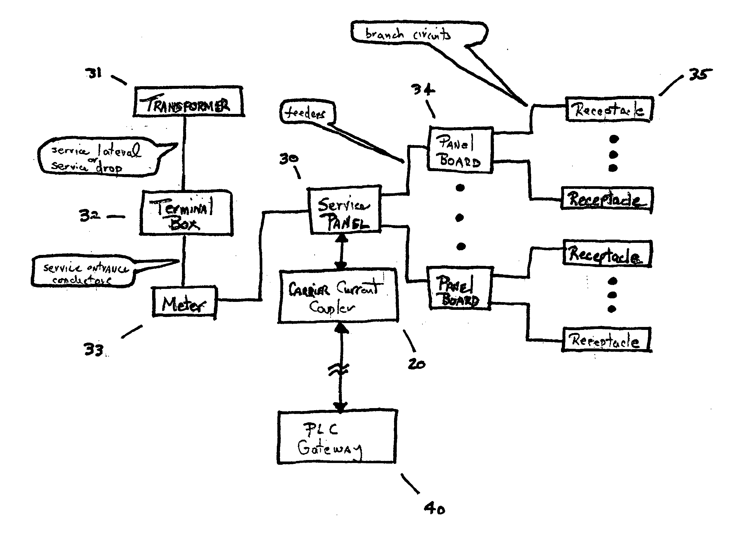
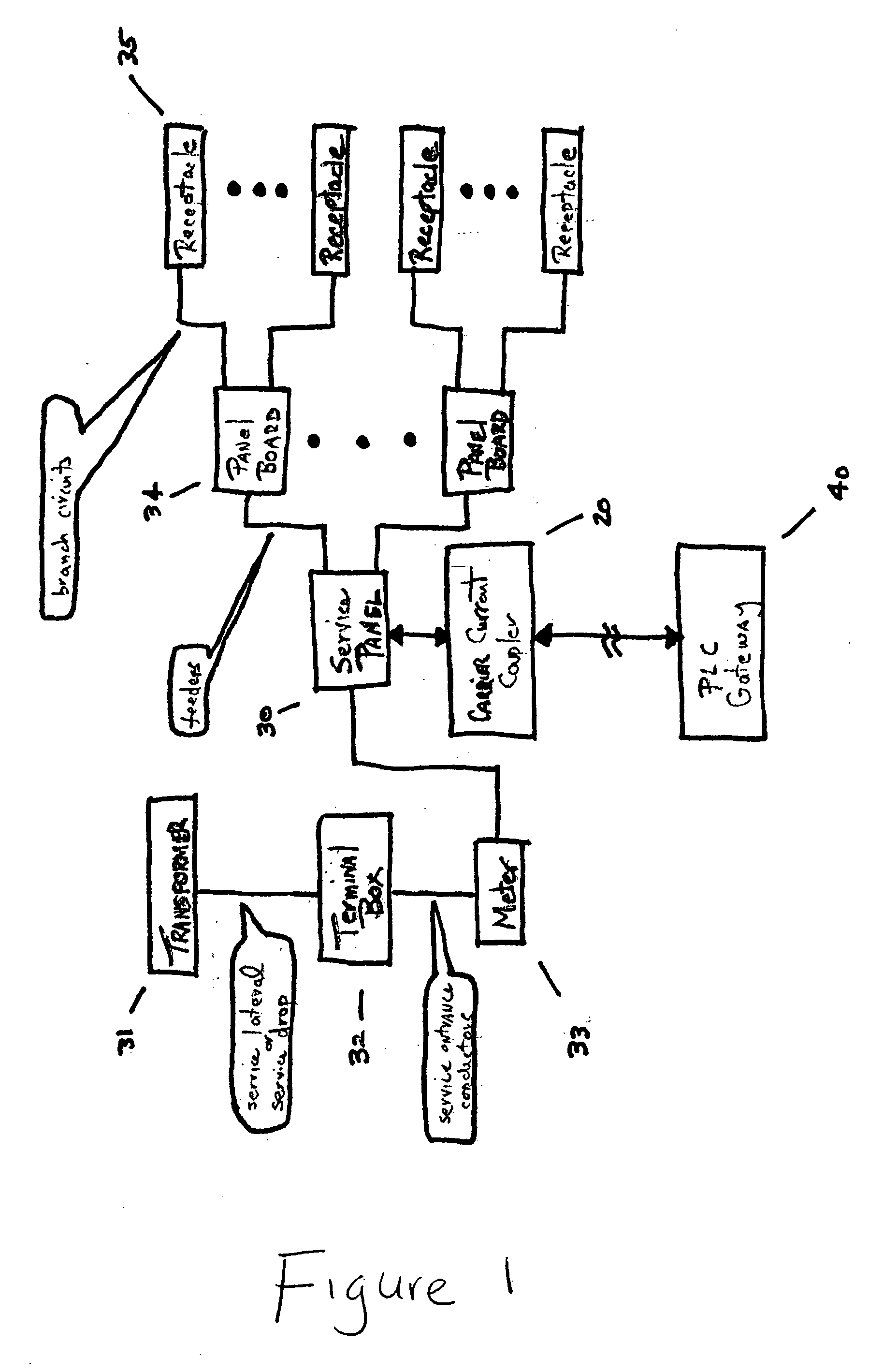
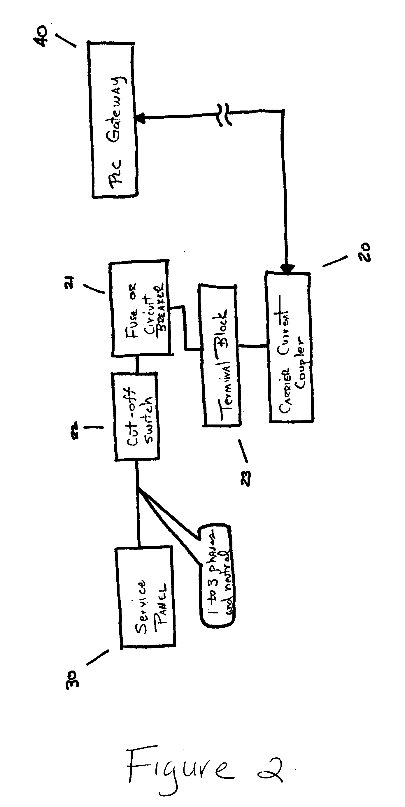
[0016] Embodiments of the current invention are directed to improving data connectivity afforded by PLC technology. While the carrier current coupler apparatus described here provides the means to effect the physical connection to the building power wiring, much of the improvement derives from identifying the appropriate point(s) at which to inject the PLC signal.

[0017] One common objective is to inject the PLC signal from a single, centralized device (often called a “gateway”) into the building wiring in such a way that all receptacles in the building receive adequate signal for a second device (often called a “terminal”) plugged in there to function properly. The attenuation of PLC signals along arbitrary runs of wiring is difficult to predict and highly variable so it is generally not possible to supply all receptacles with equal signal levels. A more achievable objective is to have the building and all of its' receptacles taken together as a system be well-behaved, i.e. where n...


PUM


Abstract

A method and apparatus for modifying a three-phase power distribution network in a building in order to provide data communication by using a Power Line Carrier (PLC) signal to an approximate electrical central location point of the power distribution system remote from the data entry point of the building. A passive coupler device is attached to a centrally located service panel. The passive coupler receives the Power Line Carrier (PLC) signal from the remote entry point in the building and conditions the signal for entry at the service panel onto each phase of the three phase power distribution network.

Description

[0001] This application claims the priority of Provisional Application Ser. No. 60 / 326,205, filed Oct. 2, 2001, the disclosure of which is expressly incorporated by reference herein.BACKGROUND AND SUMMARY OF THE INVENTION [0002] The ability to interconnect computers and other intelligent devices is a common requirement wherever people live and work today. The electrical connection required to form this local area network (LAN) has traditionally been accomplished by installing dedicated data wiring both inside buildings and between clusters of buildings. A number of wireless (i.e. radio) methods have also been developed and deployed to address this need. [0003] More recently, technology to allow electric power wiring infrastructure to simultaneously transport data at high rates has been realized. This Power Line Carrier (PLC) technology typically uses modulated radio frequency (RF) signals below 50 MHz conducted on the power wiring to transport the data. [0004] There are significant ...

Claims


Application Information

Patent Timeline
Patent Type & Authority Applications(United States)
IPC IPC(8): H04M11/04H04B3/54H04B3/56
CPCH04B3/542H04B3/56H04B2203/5483H04B2203/5445H04B2203/5466H04B2203/5433
Inventor CRENSHAW, RALPH E.GRIMES, DAVID W.LARSON, L. PETER
Owner TELKONET COMM INC
Why Eureka
Try Eureka