Recumbent bicycle

a bicycle and seat technology, applied in the field of seats, can solve the problems of inefficient bicycles, high cost and inefficiency of mounting, complicated driving and steering methods, etc., and achieve the effects of reducing the running friction of the front wheel, simple and efficient manner, and convenient bicycle peddling

Active Publication Date: 2006-01-05
RUTKOWSKI GERD
View PDF15 Cites 5 Cited by
  • Summary
  • Abstract
  • Description
  • Claims
  • Application Information

AI Technical Summary

Benefits of technology

[0008] It is the purpose of the present invention, in its simplest form, to provide a bicycle with a single steering arm on which the front wheel of the bicycle is mounted in a simple, efficient manner. In accordance with the present invention, the front wheel of the bicycle is mounted in cantilever fashion on the steering arm by a single, relatively small, annular bearing. Using a single bearing to mount the front wheel on the steering arm greatly reduces the running friction of the front wheel making it easier to peddle the bicycle and also provides a compact and lightweight wheel mounting.

Problems solved by technology

However, in both cases, the front wheel is supported by two, relatively large, spaced-apart bearings making the mounting costly and inefficient.
However, the driving and steering means are quite complicated and the driving means require the use of a number of bearings making the bicycle inefficient.
In both these bicycles however, the front wheel is supported by two spaced-apart bearings and thus is quite inefficient.
In addition, the relationship between the pedal axle and the hub of the bicycle, allowing movement of the front wheel of the bicycle relative to the pedal axle to steer the bicycle, is quite complicated and again quite inefficient.

Method used


Image

  • Recumbent bicycle
  • Recumbent bicycle
  • Recumbent bicycle

Examples


Embodiment Construction

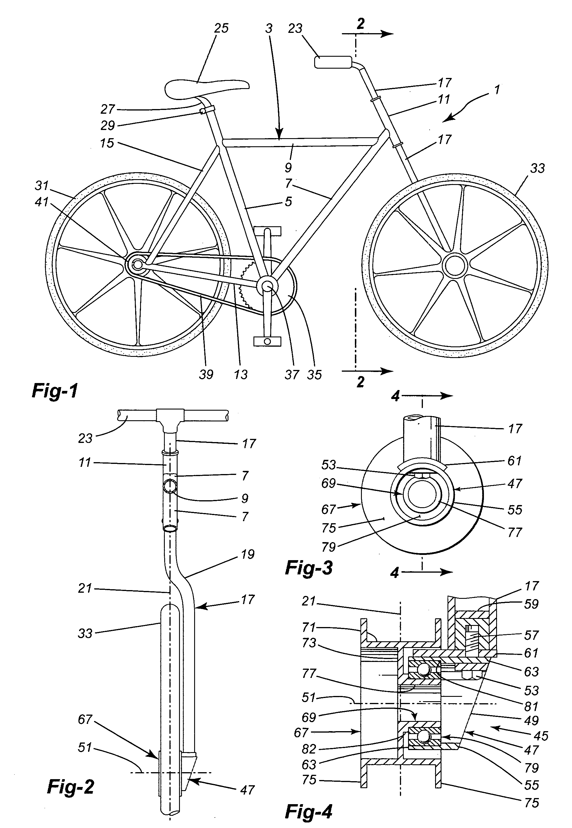
[0030] The bicycle 1 of the present invention, in one embodiment as shown in FIGS. 1 and 2, is a standard bicycle and has a frame 3. The frame 3 has an upwardly and slightly rearwardly directed seat post 5. A lower frame member 7 extends upwardly and forwardly from the bottom of the seat post 5 and an upper frame member 9 extends forwardly from the top of the seat post 5. The lower and upper frame members 7, 9 connect to a front, relatively short, steering post 11, the steering post extending downwardly and angled slightly forwardly. The frame 3 includes a first rear fork 13 extending rearwardly from bottom of the seat post 5 and a second rear fork 15 extending downwardly and rearwardly from the top of the seat post 5. The bottom end of the second rear fork 15 is joined to the back end of the first rear fork 13.

[0031] A steering arm 17 extends down through the front post 11, the arm 17 offset to one side just below the post 11, as shown at 19, to extend downwardly parallel to the l...


PUM


Abstract

A bicycle having a frame with a single steering arm rotatably mounted in the frame and extending downwardly away from the frame. A wheel support is provided at the end of the arm and a front wheel is rotatably mounted on the wheel support with a single bearing. The bicycle can have a pair of frame arms extending down from the frame with the steering arm between the frame arms and adjacent one of the arms so the front wheel is located between the arms. The frame arms carry pedal means with the axle of the pedal means passing freely through the hub of the front wheel and through the wheel support without connecting to them. Drive means are provided between the pedal axle and the front wheel for propelling the bicycle.

Description

BACKGROUND OF THE INVENTION [0001] 1. Field of the Invention [0002] This invention is directed toward a bicycle. The invention is more particularly directed toward a bicycle having a front steering wheel rotatably supported on a single steering arm. The bicycle, in a preferred embodiment, has the axle of the pedals mounted through the front wheel. [0003] 2. Description of the Related Art [0004] The front wheel of a bicycle is usually mounted between the arms of a front fork, the fork a part of the frame of the bicycle and used to steer the bicycle. The front wheel is freely rotatable in the front fork and the pedal means for propelling the bicycle is mounted on the frame behind the front wheel and connected by drive means to the rear wheel. It is known to mount the front wheel on a single support arm to provide a front wheel mount that allows easy removal of the front wheel, as shown in U.S. Pat. No. 4,170,369. It is also known to mount the front wheel on a single support arm to pro...

Claims


Application Information

Patent Timeline
Patent Type & Authority Applications(United States)
IPC IPC(8): B62M1/02B62K3/00B62K19/34B62K21/02B62K25/02B62M1/36B62M9/04
CPCB62M9/04B62K3/005B62K25/005
Inventor RUTKOWSKI, GERD
Owner RUTKOWSKI GERD
Why Eureka
Try Eureka