Dual seating quick connect valve

a quick connection, valve technology, applied in the direction of functional valve types, couplings, transportation and packaging, etc., can solve the problems of only passing fluid, inability to stop fluid flow, and limit the ability of sealing an orifice, so as to improve the sealing of an orifice in a simple and efficient manner

Inactive Publication Date: 2011-12-27
EASTMAN KODAK CO
View PDF14 Cites 13 Cited by
  • Summary
  • Abstract
  • Description
  • Claims
  • Application Information

AI Technical Summary

Benefits of technology

[0007]The present invention is directed to overcoming one or more of the problems associated with currently known valves set forth above. Briefly summarized, according to one aspect of the present invention, is provided an elastomeric valve having a dual seating feature for improved sealing of an orifice when the valve is in a closed state. The fluid valve maintains a positive seal and prevent fluid flow until actuated by a means such as a mechanical force which displaces a portion of the valve in an axial direction thereby allowing free fluid flow in either direction through the valve. The valve returns to its original closed state once the means for actuating the valve are removed, resulting in a quick connecting valve that can be repeatedly opened and closed in a simple and efficient manner.
[0010]According to another aspect of the invention, a method of controlling fluid flow includes providing a container, portions of the container defining a hole; providing a valve seated in the hole, the valve including: a stem including a first sealing portion, the stem having a longitudinal axis; a cap connected to the stem, the cap including a passageway; and a deformable lip extending from a periphery of the cap, the deformable lip including a second sealing portion, the stem being displaceable relative to the deformable lip along the longitudinal axis of the stem to open the first sealing portion and close the second sealing portion to allow fluid to move through the passageway in the cap; and displacing the stem relative to the deformable lip along the longitudinal axis of the stem to open the first sealing portion and close the second sealing portion causing fluid to move through the passageway in the cap.

Problems solved by technology

Such applications can be relatively basic such as containing a fluid in an enclosure until it is intended for some use while others can be complicated such as in an apparatus or process used in a medical, industrial or automotive application, just to name a few.
Valves of the type where liquid pressure actuates the valve to allow fluid flow often suffer from limitations in their ability to seal an orifice from leakage and are, by design, not able to stop fluid flow under some critical level of fluid pressure.
A further limitation of the known valve designs is that fluid can only flow past or through the valve in the one direction that the fluid is moving.

Method used


Image

  • Dual seating quick connect valve
  • Dual seating quick connect valve
  • Dual seating quick connect valve

Examples


Embodiment Construction

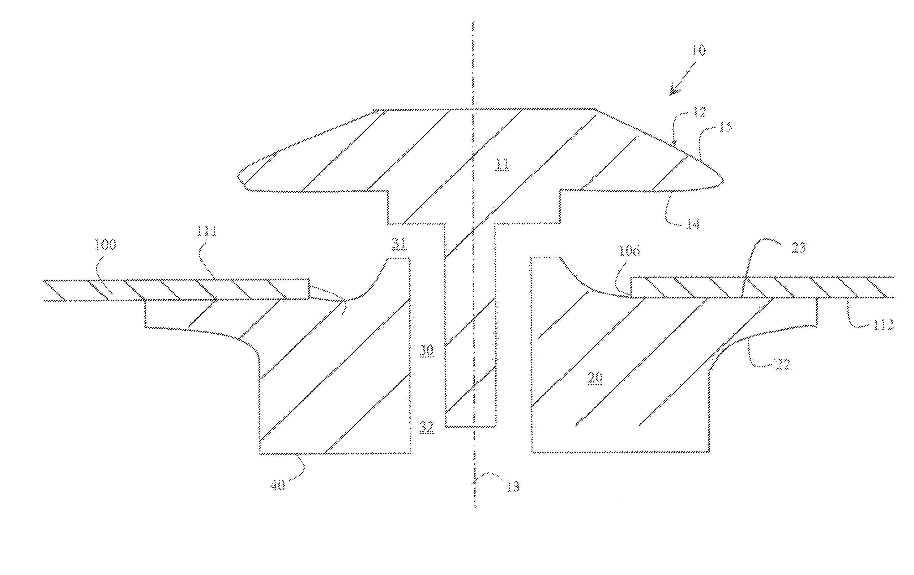
[0019]Valves of the present invention are made from elastomeric materials and in particular thermoplastic elastomeric polymers. Elastomeric polymers useful in the present invention include those selected from the non-exhaustive list consisting of, polyisoprene, polybutadiene, polychloroprene, polyisobutylene, poly(styrene-butadiene-styrene), polyurethanes, silicones, poly(bis(fluoroalkoxy)phosphazene) (PNF, Eypel-F), poly(carborane-siloxanes) (Dexsil), poly(acrylonitrile-butadiene) (nitrile rubber), poly(1-butene), poly(chlorotrifluoroethylene-vinylidene fluoride) copolymers (Kel-F), poly(ethyl vinyl ether), poly(vinylidene fluoride), poly(vinylidene fluoride-hexafluoropropylene)copolymer (Viton), elastomeric compositions of polyvinylchloride (PVC), polysulfone, polycarbonate, polymethylmethacrylate (PMMA), and polytertrafluoroethylene (Teflon), or combinations thereof. It is possible to crosslink the elastomeric polymers using known crosslinking chemistries. The valve can also incl...


PUM


Abstract

A valve includes a stem, a cap, and a deformable lip. The stem includes a first sealing portion and has a longitudinal axis. The cap is connected to the stem and includes a passageway. The deformable lip extends from a periphery of the cap and includes a second sealing portion. The stem is displaceable relative to the deformable lip along the longitudinal axis of the stem to open the first sealing portion and close the second sealing portion to allow fluid to move through the passageway in the cap.

Description

FIELD OF THE INVENTION[0001]The invention relates generally to the field of fluid flow, and in particular to elastomeric valves.BACKGROUND OF THE INVENTION[0002]Numerous applications exist where the regulation of fluid flow through an orifice is required. Such applications can be relatively basic such as containing a fluid in an enclosure until it is intended for some use while others can be complicated such as in an apparatus or process used in a medical, industrial or automotive application, just to name a few. The typical name for a component which regulates fluid flow is a valve and nearly all valves have two principal functions. The first function is stop fluid flow through an orifice without causing any leakage past the valve and the second function is to allow the liquid to flow freely through the orifice upon actuation of the valve.[0003]Traditionally, the regulation of fluid flow has been accomplished using various valve designs. A number of known valve designs include, bal...

Claims


Application Information

Patent Timeline
Patent Type & Authority Patents(United States)
IPC IPC(8): B41J2/175F16K21/04
CPCF16K15/148B41J2/17596Y10T137/7879Y10T137/7933
Inventor PRICE, BRIAN G.SCOTT, DAVID R.
Owner EASTMAN KODAK CO
Why Eureka
Try Eureka