Wire cutting and twisting tool with spool assembly and manual wire feeding mechanism

Inactive Publication Date: 2006-03-02
CHENG DARA
View PDF20 Cites 3 Cited by
  • Summary
  • Abstract
  • Description
  • Claims
  • Application Information

AI Technical Summary

Benefits of technology

[0009] It is therefore an object of this invention to provide an inexpensive, simple and efficient method of cutting and twisting cutting wire with a tool that is ergonomically comfortable and efficient, and can be used without reliance on electrical or battery power.
[0011] It is an additional object of this invention that the wire inside the body cavity of the tool is protected from dirt and debris by the tool body, and that the wire inside the body cavity is not twisted by the tool.

Problems solved by technology

Taking the ends of a piece of wire and twisting them by hand is an extremely time-consuming and strenuous task.
U.S. Pat. No. 5,836,137 to Contreras (1998) teaches an intermittent rotable pneumatic drive which gathers material around an article for tying, but this machine is expensive, cannot be operated by hand, and would not be convenient to use in a construction setting where a small hand tool would be much more convenient.
U.S. Pat. Nos. 3,091,264 to Stanford (1963), 3,593,759 to Wooge (1971), and 4,448,225 to Schmidt (1984) teach hand tools which would be convenient to use on a construction site, but require as part of their operation that the supply wire be twisted, thereby creating a potential for jamming problems with the supply wire.
U.S. Pat. No. 5,501,251 to Vader (1996) teaches a hand tool which has a supply of wire which is twisted by the tool and cut by additional pulling on the tool, but this tool is not ergonomically designed, requires an external source of wire, thereby decreasing its ease of use, and requires the addition of a commercially available ratchet spring return twister rather than having the twisting mechanism built into the tool.

Method used


Image

  • Wire cutting and twisting tool with spool assembly and manual wire feeding mechanism
  • Wire cutting and twisting tool with spool assembly and manual wire feeding mechanism
  • Wire cutting and twisting tool with spool assembly and manual wire feeding mechanism

Examples


Embodiment Construction

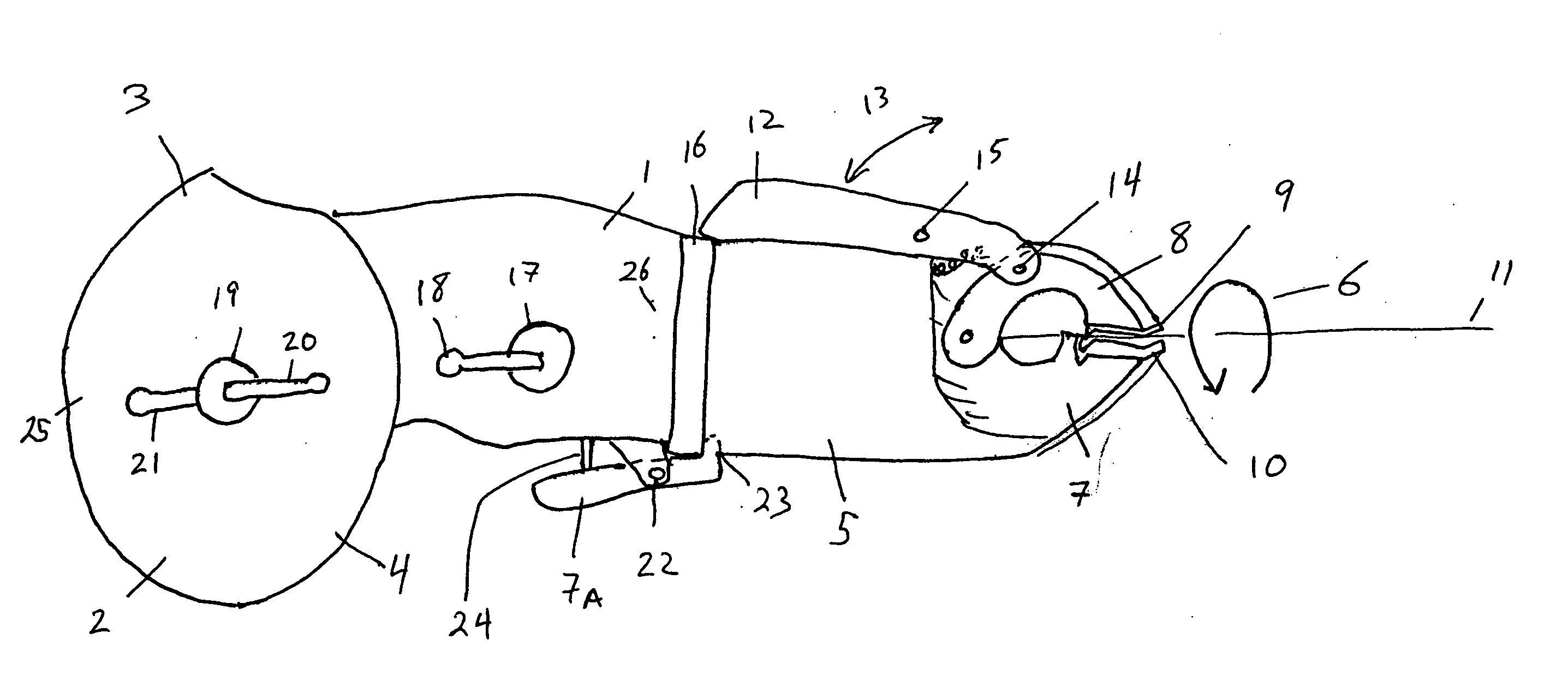
[0017] The present invention is directed to a tool which can easily and efficiently twist and cut wire which is fed through the jaws of the tool by means of a spooling assembly and a cranking mechanism.

[0018] Referring to the drawings the invention consists of a spool of wire held inside of the tool body, where the wire is fed out through the jaws of tool where the wire is cut, and a series of grooves and steel balls allows the wire to be twisted by the rotating tool head. The tool consists of four detachable parts, a tool body in which the spool is located, the tool head portion where the jaws and grooves are located, a locking ring which attaches the head portion to the tool body, and two steel balls which sit in indentations in the tool body and cause the head portion to spin and twist the wire before it is cut.

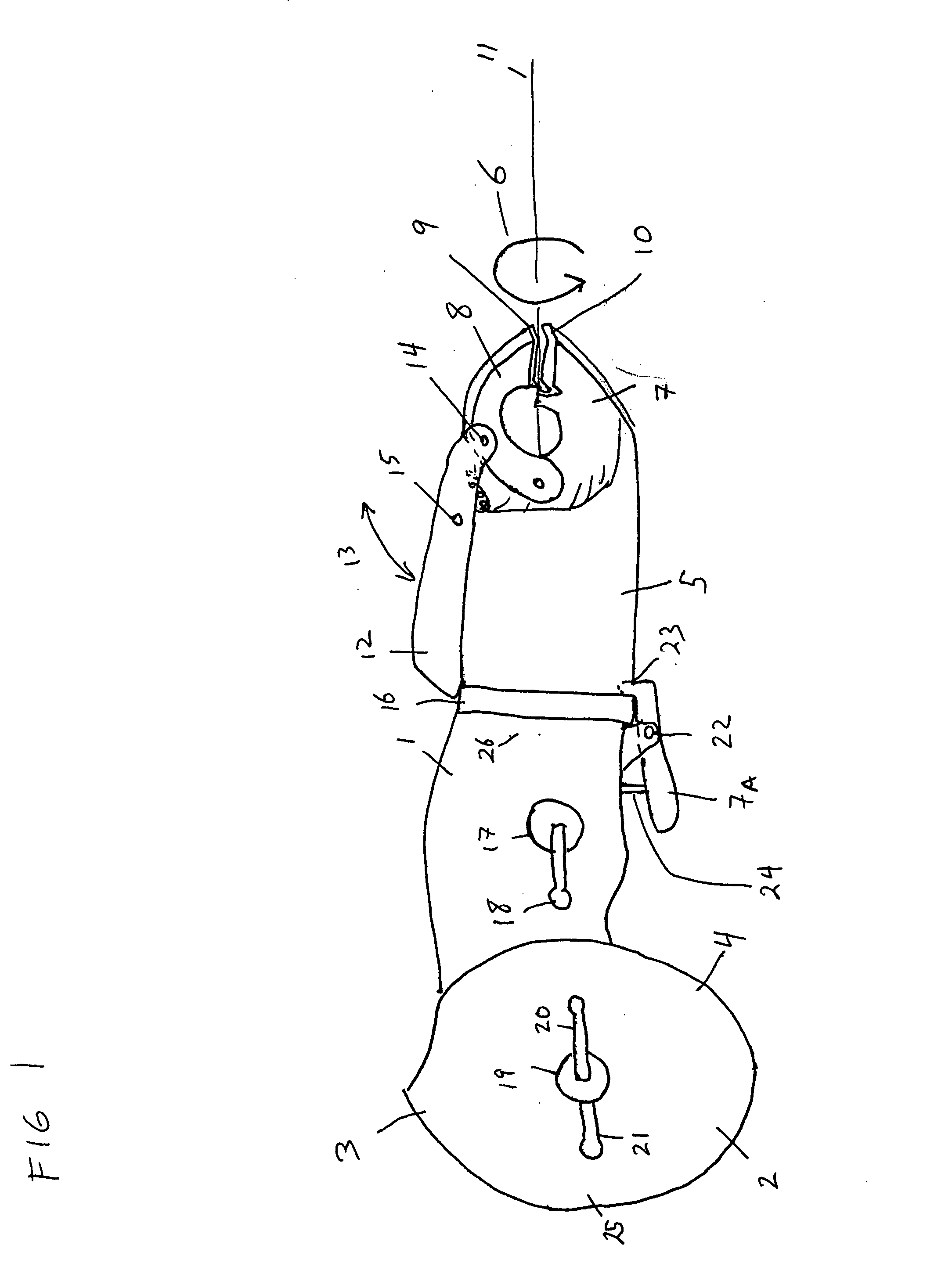
[0019]FIG. 1 is a side view of the tool. The tool consists of four parts, three of which are visible here. A tool body (1) is comprised of two tool body parts, the right...


PUM

PropertyMeasurementUnit
Angleaaaaaaaaaa
Frictionaaaaaaaaaa

Abstract

A wire twisting tool with a spool assembly, locking mechanism, manual wire feeding mechanism, and cutting jaws is claimed. The tool is designed to quickly and efficiently cut wire and twist it, utilizing a series of matching grooves into which are placed two steel balls which allow the cutting and twisting head portion to rotate about the body portion as the body portion is pulled back by a user.

Description

CROSS REFERENCE TO RELATED APPLICATIONS [0001] None. STATEMENT REGARDING FEDERALLY SPONSORED RESEARCH OR DEVELOPMENT [0002] This invention was not federally sponsored. BACKGROUND OF INVENTION [0003] Tools to cut wire have been popular for centuries, as have been wire twisting devices. These types of tools are commonly used in construction, where wire is used to attach two pieces of rebar prior to pouring slabs or columns. Wire twisting and cutting devices are also frequently used to attach fences to posts, repair holes in fences, and wire pieces of reinforcing bar together when pouring concrete slabs and making concrete posts and ceilings. Taking the ends of a piece of wire and twisting them by hand is an extremely time-consuming and strenuous task. [0004] While the prior art has examples of tools which are designed to cut and twist wire, the current invention is the first to combine in an inexpensive hand tool an ergonomic fit, a method of regulating the output and intake of wire, ...

Claims


Application Information

Patent Timeline
IPC IPC(8): B21F23/00
CPCB21F15/04E04G21/122E04G21/123
Inventor CHENG, DARA
Owner CHENG DARA
Why Eureka
Try Eureka