Unlock instant, AI-driven research and patent intelligence for your innovation.

Powder coating for generator stator bar end fitting and method for applying the power coating

a stator bar end fitting and power coating technology, which is applied in the direction of windings, manufacturing tools, and so on, can solve the problems of corrosion and subsequent leakage, water can corrode copper alloy, and the connection between the stator bar end and the stator bar fitting as well as between adjacent strands, so as to improve repeatability and reproducibility, reduce labor and cycle time, and improve coverage

Inactive Publication Date: 2006-05-18
GENERAL ELECTRIC CO
View PDF31 Cites 3 Cited by
  • Summary
  • Abstract
  • Description
  • Claims
  • Application Information

AI Technical Summary

Benefits of technology

[0008] Powder coating is proposed in an embodiment of the invention to coat the stator bar clip interior, irrespective of configuration, the braze alloy, and the solid strands without clogging the hollow strands. Thus, the invention proposes a powder coating method to deposit a thin layer on the interior surface of a liquid-cooled stator bar clip. The powder coat layer provides a corrosion resistant barrier coating to prevent water access to corrosion susceptible region(s) such as clip-to-strand braze joints. In contrast to the epoxy coating method of the '590 patent, powder coating reduces labor and cycle time for coating a stator bar clip, provides improved coverage without the risk of plugging hollow cooling strands; has improved repeatability and reproducibility independent of a technicians skill level and increases reliability of the stator bar in service.

Problems solved by technology

Water can corrode the copper alloy.
Also, over time, leaks can develop about the connection between the stator bar ends and the stator bar fitting as well as between adjacent strands.
This coolant contact with the braze joint and copper strands is believed to cause corrosion and consequent leakage.
This is particularly true if the leak is occurring between the strands of the stator bar.
Thus, the process is labor intensive and requires 100% inspection.
As a result, the process can be labor intensive, takes a long time to complete, and can produces defects.

Method used


Image

  • Powder coating for generator stator bar end fitting and method for applying the power coating
  • Powder coating for generator stator bar end fitting and method for applying the power coating
  • Powder coating for generator stator bar end fitting and method for applying the power coating

Examples


Embodiment Construction

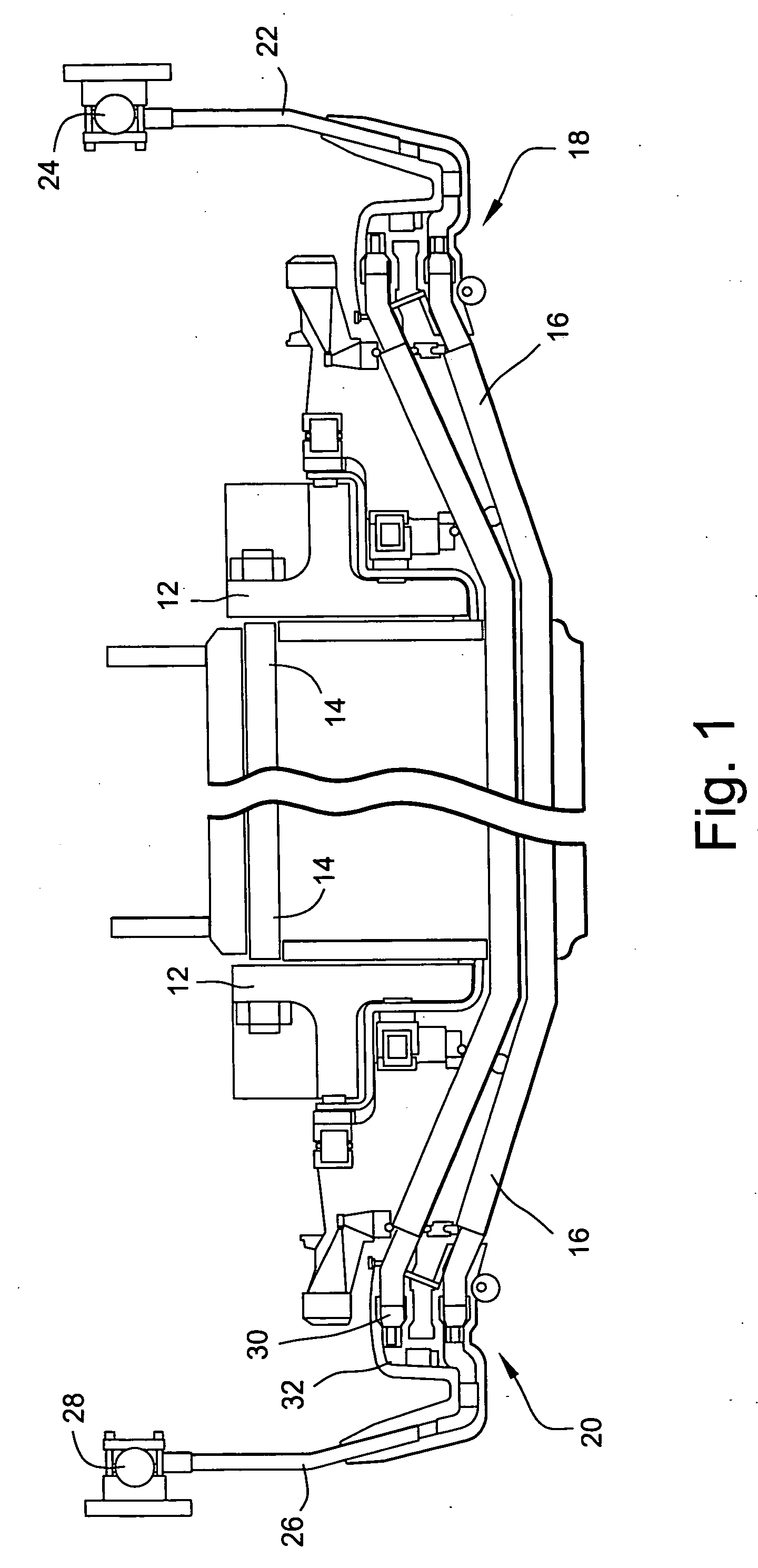
[0019] Water-cooled stator bars for electrical generators are comprised of a plurality of small rectangular solid and hollow copper strands which are brazed to one another and brazed to an end fitting. The end fitting serves as both an electrical and a hydraulic connection for the stator bar. The end fitting typically includes an enclosed chamber for ingress or egress of stator bar cooling liquid, typically deionized water. One end of the end fittings, more specifically the stator bar clip receives the ends of the strands of the stator bar, the clip and peripherally outermost copper strands of the stator bar being brazed to one another. Over time, leaks have variously developed about the connection between the stator bar ends and the stator bar clip as well as between adjacent strands. It is believed, based on leak analysis results, that the leak mechanism is due to a corrosion process which initiates in the braze alloy at the interior surface of the braze joint. Stagnant water in c...


PUM

PropertyMeasurementUnit
thicknessaaaaaaaaaa
thicknessaaaaaaaaaa
liquidus temperatureaaaaaaaaaa

Abstract

A method of sealing a generator stator bar and a stator bar end fitting receiving the end including the steps of: brazing the fitting to the end of the stator bar with a braze material; applying a powder coating material to the end of the stator bar in the fitting; and curing the powder coating material to form a barrier coating on the end of the stator bar and the adjoining interior surfaces of the fitting.

Description

BACKGROUND OF THE INVENTION [0001] The present invention relates to seals between generator stator bars and their end fitting connections, and to a method for sealing a stator bar end fitting to prevent or reduce corrosion due to coolant water flowing through the fitting and the stator bar. [0002] Water-cooled stator bars for electrical generators are comprised of a plurality of small rectangular solid and hollow copper strands brazed to one another to form a bar. The ends of the strands are brazed to an end fitting, typically referred to as stator bar clip. The end fitting serves as both an electrical and a cooling flow connection for the stator bar. [0003] The hollow end fitting typically includes an enclosed chamber for ingress or egress of stator bar cooling liquid, typically deionized water. At one end, the end fitting receives the ends of the strands of the stator bar. The fitting and the peripherally outermost copper strands of the stator bar are brazed to one another. The op...

Claims


Application Information

Patent Timeline
Patent Type & Authority Applications(United States)
IPC IPC(8): B23K31/00
CPCH02K3/44Y10T29/49009H02K15/12H02K15/0093
Inventor MALL, WAHEED TONYLUSTED, RODERICK MARKWANG, YU
Owner GENERAL ELECTRIC CO