Push latch

a technology of push latches and latches, which is applied in the direction of fastening means, carpet fasteners, mechanical devices, etc., can solve the problems of high assembly cost, requiring the assembler to start all, so as to reduce the number of components, the effect of reducing the number of components

US20060103140A1Active Publication Date: 2006-05-18ILLINOIS TOOL WORKS INC
4 Cites 27 Cited by

Patent Information

Authority / Receiving Office
US · United States
Patent Type
Applications(United States)
Current Assignee / Owner
Publication Date
2006-05-18

Smart Images

  • Figure 1
    Figure 1
  • Figure 2
    Figure 2
  • Figure 3
    Figure 3
Patent Text Reader

Abstract

A push latch that may be used in automobile applications to open and close compartment doors or bins reduces the number of components typically found in prior art designs while retaining the same quality and function. The push latch of the invention further eliminates the use of metal pins and springs, provides an assembly that is easier to assemble and reduces the cost to manufacture. In one embodiment, the push latch generally includes the use of a housing, lock and button. The lock includes the use of a flexible spring arm and bosses, which will engage with cam slots in the button. In operation, when the button is pushed, the cam slots will force the bosses and the lock downward causing the release of the compartment door. When the button is released, the flexible spring arm forces the cylindrical bosses upward in the cam slots thus forcing the button and lock back to their original positions.
Need to check novelty before this filing date? Find Prior Art

Description

CROSS REFERENCE TO RELATED APPLICATIONS

[0001] This Non-Provisional Application claims benefit to U.S. Provisional Application Ser. No. 60 / 629,043 filed Nov. 18, 2004FIELD OF THE INVENTION

[0002] The present invention relates generally to push latches and more specifically to push latches that may be used in automobile applications for glove boxes, cup holders, receptacle bins, and the like. BACKGROUND OF THE INVENTION

[0003] It is known that push latches are used in automobiles to open and close compartments such as glove boxes, cup holders and receptacle bins. Many of these known latch mechanisms use a “push-push” configuration. With this configuration, the mechanism becomes latched by a pushing action from the user, and becomes unlatched by a similar or identical pushing motion. Other latch mechanisms use a “push-release” configuration. With this configuration, the mechanism is latched and becomes unlatched by a pushing and releasing action from the user. One known push latch inc...

Examples

Embodiment Construction

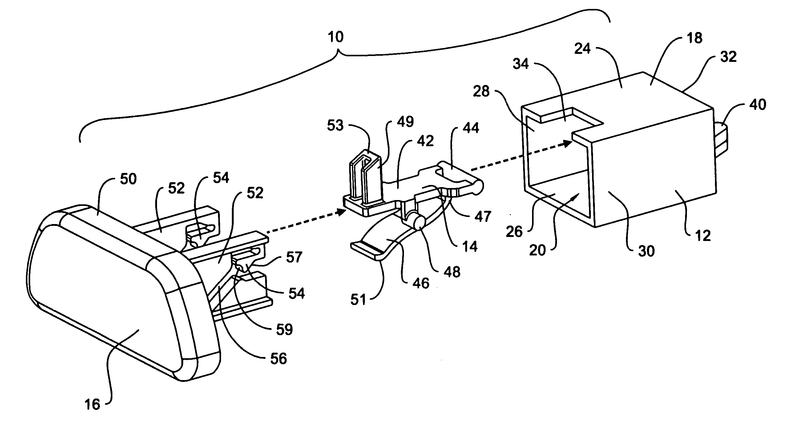
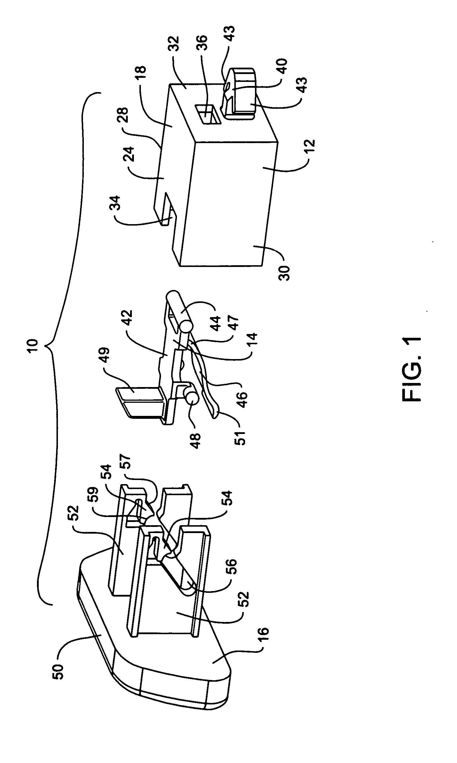
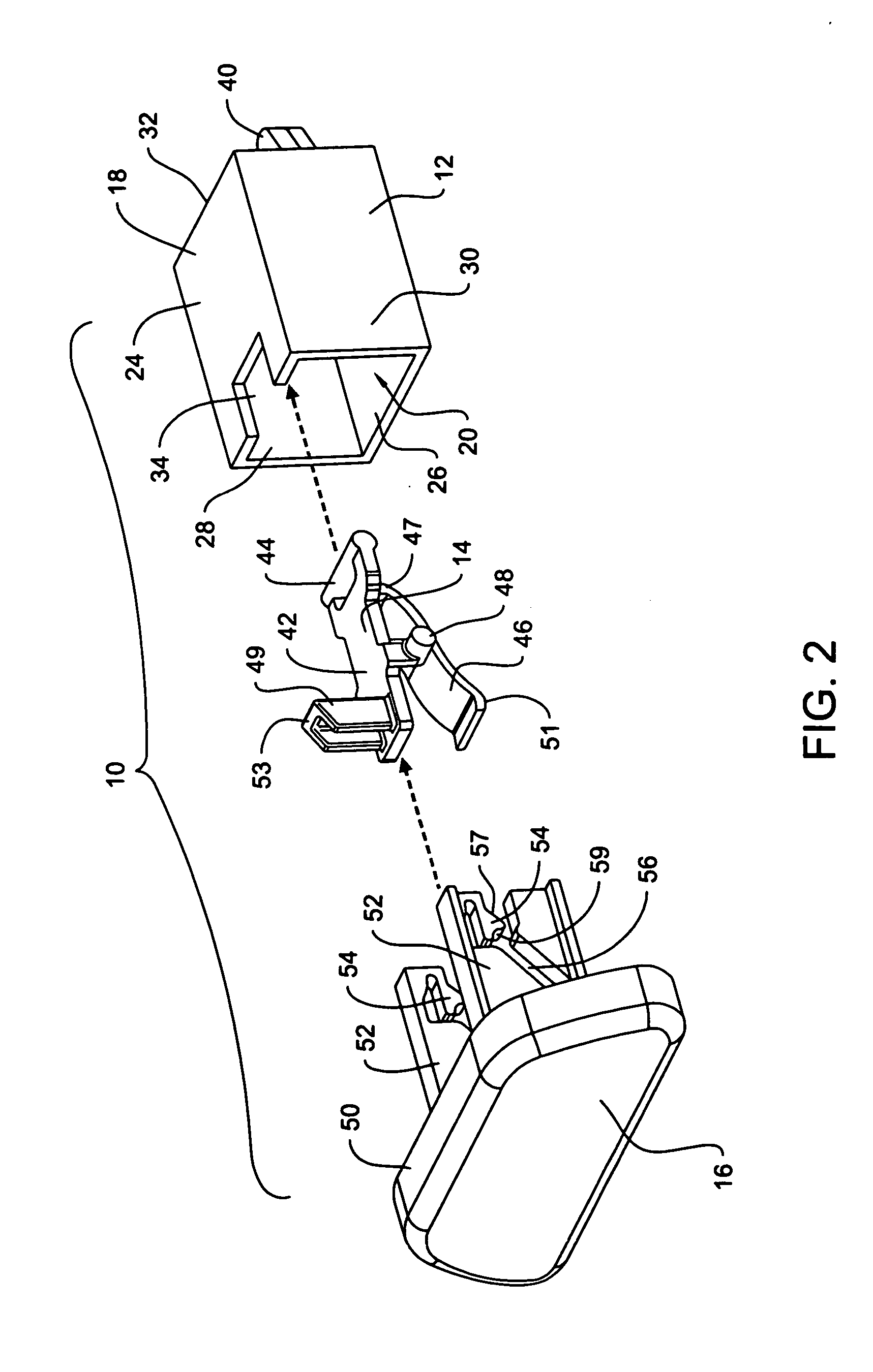
[0020] Referring to FIGS. 1 and 2, an exploded view of an exemplary embodiment of the push latch 10 of the invention is depicted and includes an exemplary housing 12, a lock 14, and a button 16. The structure and relationship of these exemplary components are described below. The exemplary housing 12 defines a box shaped housing body 18 made from a plastic or other suitable material. The housing body 18 forms a cavity 20 defined by a top wall 24, a bottom wall 26, a first side wall 28, a second side wall 30, and a back wall 32. The top wall further defines a notch 34 through which extends a lock boss 49, as described below. The back wall 32 defines an opening 36. Referring to FIG. 3a, positioned on opposing sides of the opening 36 and extending into the cavity 20 are snaps or flexible retaining members 38. The snaps 38 serve to mount the lock 14 to the housing, as described below, and permit pivotal movement of the lock 14 within the housing. The snaps 38 extend in a generally paral...