
Motor vehicle latch

a technology for motor vehicles and latches, applied in the direction of fastening means, non-mechanical controls, power transmission/actuator features, etc., can solve the problems of difficult control of the expansion of the springs to obtain stable kinematic positions, the weighty and costly of the latches, and the inability to achieve the precise stop position relative to the precision required of the mechanism to be used

Inactive Publication Date: 2006-05-18
ARVINMERITOR LIGHT VEHICLE SYST FRANCE
View PDF18 Cites 29 Cited by
  • Summary
  • Abstract
  • Description
  • Claims
  • Application Information

AI Technical Summary

Problems solved by technology

The drawback of these latches is that they have a large number of parts for the required operations (motors and transmission gears), making these latches bulky and costly.
The drawback of this latch is the imprecision of the stop position reached relative to the precision required of the mechanisms to be used.
The drawback of the use of springs is the difficulty in controlling the expansion of the springs to obtain stable kinematic positions.

Method used


Image

  • Motor vehicle latch
  • Motor vehicle latch
  • Motor vehicle latch

Examples


first embodiment

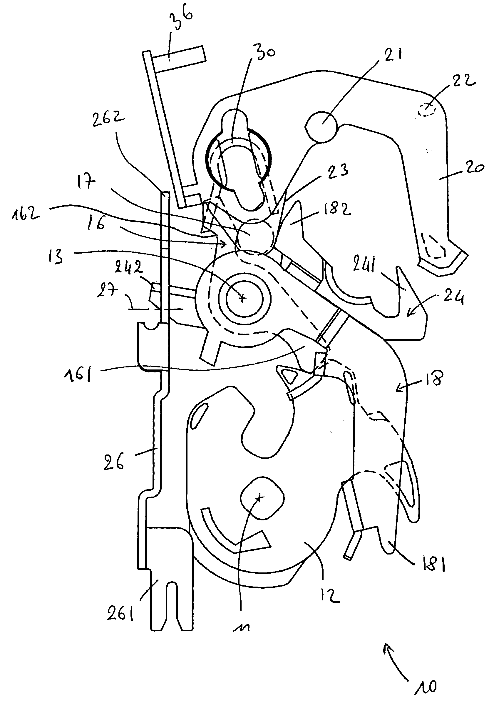
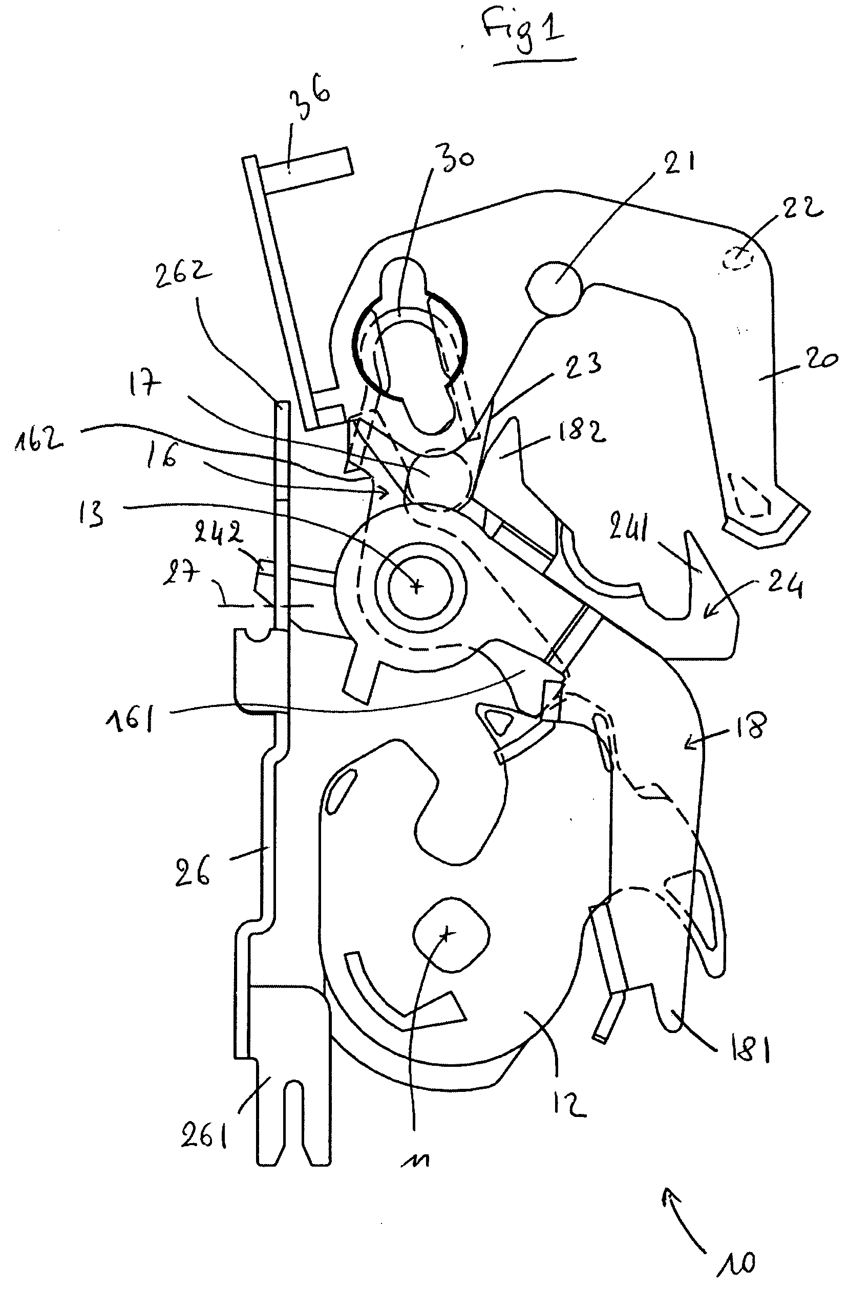
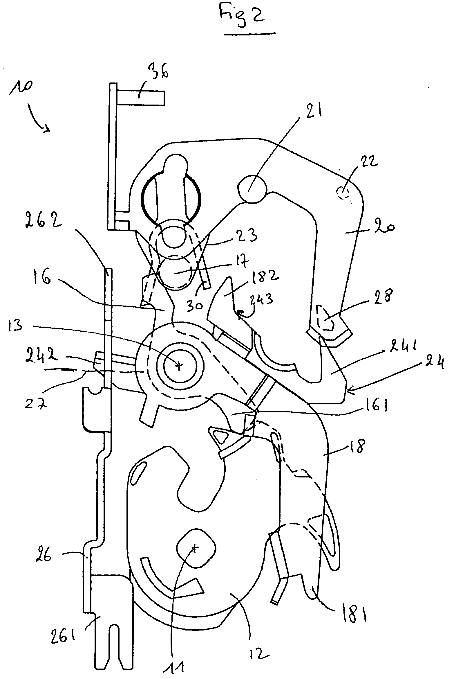
[0057] The operation of the latch 10 will now be described. the latch 10 can change from a first state to a second state by moving the mobile part 40 in the first direction. During this change in state, the stop 46 remains in the first position. Moving the mobile part 40 causes a change in the position of the locking arm 20, which changes the state of the latch 10.

[0058] The latch 10 can then change from the second state to a third state. First of all, in order to do this, the mobile part 40 is moved in the second direction to cause the stop 46 to move from the first position to the second position. Secondly, the mobile part 40 is moved in the first direction, and the stop 46 then remains in the second position. The last movement of the mobile part 40 causes a change in the position of the locking arm 20, which changes the state of the latch 10.

[0059] The latch 10 can then change from the third state to the first state. In order to do this, the mobile part 40 is moved in the secon...

second embodiment

[0060] the latch 10 can change from a first state to a second state by moving the mobile part 40 in the first direction. During this change of state, the stop 46 is moved from the second position to the first position. The movement of the mobile part 40 causes a change in the position of the locking arm 20, which changes the state of the latch 10.

[0061] The latch 10 can then change from the second state to a third state. First, the mobile part 40 is moved in the second direction. The movement of the mobile part 40 causes the movement of the stop 46 from the first position to the second position. Secondly, the mobile part 40 is moved in the first direction, and the stop 46 then remains in the second position. The last movement of the mobile part 40 causes a change in the position of the locking arm 20, which changes the state of the latch 10.

[0062] The latch 10 can then change from the third state to the first state. In order to do this, the mobile part 40 is moved in the second di...


PUM


Abstract

A latch includes an external opening lever and an internal opening lever. The latch is designed to occupy three states of locking and / or unlocking of the levers. The latch includes a locking arm mobile between three positions corresponding to the three states of the latch, a mobile part moveable by actuation of a motor in a first direction and a second direction and a stop moveable between a first position and a second position. The stop is mounted on the mobile part, and the stop and the mobile part drive the locking arm. The latch is able to pass through the three states by moving the mobile part in its two directions and by moving the mobile stop between its two positions.

Description

REFERENCE TO RELATED APPLICATION [0001] This application claims priority to French Patent Application FR 04 12 027 filed on Nov. 12, 2004. BACKGROUND OF THE INVENTION [0002] The invention relates generally to the field of motor vehicle latches. [0003] Latches allow for an opening of a motor vehicle to be held in a closed position. They also allow for the opening to be opened by action on an internal or external opening control connected to the latch that can be activated by a user. Such a latch is typically mounted on the opening of the vehicle. The latch includes a claw that functions to secure a striker mounted on the vehicle relative to the latch or by contrast to release the striker. Releasing the striker allows the opening to be opened and is called opening the latch. Conversely, holding the striker in the latch prevents the opening from being opened and is called closing the latch. The claw is forced towards the closed position by the striker when the opening is closed, and a ...

Claims


Application Information

Patent Timeline
IPC IPC(8): E05C3/06
CPCE05B63/0069E05B81/14E05B81/34E05B81/42E05B2047/0036Y10T292/1047
Inventor OTTOLINI, PHILIPPEBURKAT, FREDERICBELMOND, JEAN-MARC
Owner ARVINMERITOR LIGHT VEHICLE SYST FRANCE
Learn More