Micro-pleated stent assembly

a stent and micro-pleated technology, applied in the field of medical and veterinary stents, can solve the problems of reducing the solid area but not by a percentage great enough to reduce the effectiveness, and achieve the effects of effective treatment of a greater percentage of aneurysms, less invasiveness, and less invasiveness

Inactive Publication Date: 2006-07-13
HINES RICHARD ALLEN
View PDF31 Cites 71 Cited by
  • Summary
  • Abstract
  • Description
  • Claims
  • Application Information

AI Technical Summary

Benefits of technology

[0026] The stent of the present invention is well suited to affect a cure of neurovascular aneurysms, to a greater extent than the mechanism described in the '527 application, because it gives the physician more control over the stent expansion, allowing for a more optimal fit within the artery and over the aneurysm. For example, if an artery is 3 mm in diameter on one end of the aneurysm and 4 mm in diameter on the other end of the aneurysm, the ability to expand the stent to fit 3 mm on one end of the stent and 4 mm on the other end of the stent provides a tailored fit within the artery and thus the ability to effectively treat a greater percentage of aneurysms. The micro-pleated stent assembly of the present invention can be used to treat most aneurysms, including berry, or saccular, aneurysms and fusiform aneurysms located in the neurovascular arteries, in the abdominal aortic artery and other arteries.
[0027] The stent of the present invention has more longitudinal flexibility than the pleated stents described in the '527 application because the diameter of the crimped micro-pleats is smaller and because the balloon may be shorter and more compliant. A short, more compliant, balloon may be used because it is not necessary to expand the entire stent with one balloon expansion. Additional flexibility will ensue because the stent is not pleated onto and with the balloon, decoupling the two, allowing more relative movement to improve flexibility.
[0028] The micro-pleated stent assembly of the present invention may be used in conventional stenting applications, as well as in applications wherein stenting has not been successful due to limitation of current stents and stent delivery systems. The primary application of this stent would be for a neurovascular aneurysm; however, it can be used in place of the current standard coronary stents with the additional advantage of providing a more solid area.
[0029] Using a number of different metals and alloys, the micro-pleated stent can also be designed with variable levels of radiopacity. Increasing the radiopacity will make a stent more viewable to X-rays. Less radiopacity will allow a better X-ray view of tissue growth within the stent. By using various combinations of metals and alloys, the micro-pleated stents can be designed with different levels of radiopacity, based on the desired radiopacity for a particular purpose. Neurovascular stents typically need highly radiopaque material because they are thin and because of the bone mass they must be imaged through. Coronary stents may not require a highly radiopaque material because they are typically thicker and there is less bone mass to deal with.

Problems solved by technology

After unpleating, further expansion through use of the compliant balloon decreases the solid area but not by a percentage great enough to reduce effectiveness.

Method used


Image

  • Micro-pleated stent assembly
  • Micro-pleated stent assembly
  • Micro-pleated stent assembly

Examples


Embodiment Construction

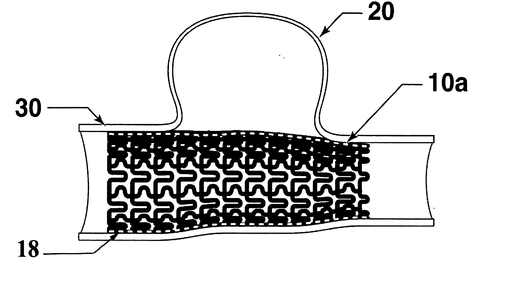
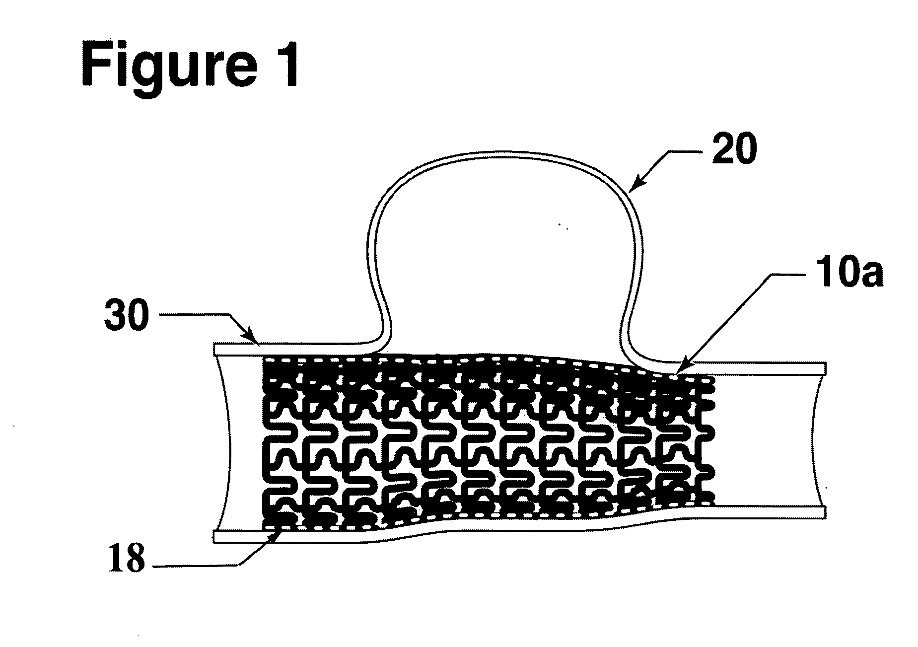
[0058] The present invention is directed to a micro-pleated stent, typically unpleated and expanded with an elastic balloon shorter than the stent. The unique features of the micro-pleated stent system results in the placement of a stent having a large percent solid area over the neck of an aneurysm. The stent pattern and the use of a short elastic balloon and multiple balloon expansions allow the stent to be expanded to a non-cylindrical shape to conform to the artery shape that frequently exist at the site of an aneurysm. The stent sufficiently blocks circulation into the aneurysm so as to cause a thrombus to form in the aneurysm to eliminate the danger of bursting. As the thrombus is absorbed, the aneurysm volume shrinks thus reducing pressure on surrounding tissue.

[0059]FIG. 1 shows a longitudinal cross-section of the stent 10a deployed at the site of an aneurysm 20 within the artery 30. Micro-pleated stents may be designed and used in arteries as small as about 2 mm diameter o...


PUM


Abstract

The present invention is directed to a micro-pleated medical device assembly, preferably a micro-pleated stent assembly, comprising a tube micro-pleated to a delivery diameter suitable for intraluminal delivery. The micro-pleated stent assembly of the present invention is designed to have a substantially solid wall, and is thus particularly suited for the treatment of neurovascular aneurysms, having the ability to block the neck of an aneurysm. Sections of the micro-pleated stent may be selected for expansion to variable diameters in order to optimally fit the configuration of the vessel.

Description

CROSS-REFERENCE TO RELATED APPLICATIONS [0001] Not Applicable. STATEMENT REGARDING FEDERALLY SPONSORED RESEARCH OR DEVELOPMENT [0002] Not Applicable. COPYRIGHT NOTICE [0003] A portion of the disclosure, including the figures, contains material which is subject to copyright protection. The copyright owner has no objection to the facsimile reproduction by anyone of the patent document or the patent disclosure, as it appears in the Patent and Trademark Office patent file or records, but otherwise reserves all rights whatsoever. TECHNICAL FIELD [0004] The present invention is directed to the field of medical and veterinary stenting for endovascular treatments and, more particularly, treatment of neurovascular aneurysms. BACKGROUND OF THE INVENTION [0005] A stent is a tubular medical device typically inserted into the lumen of a vessel, or other organ, to open the vessel and / or maintain the vessel in an open position to maintain flow within the vessel. [0006] Stents can be balloon-expand...

Claims


Application Information

Patent Timeline
Patent Type & Authority Applications(United States)
IPC IPC(8): A61F2/06A61F2/82
CPCA61F2/844A61F2/91A61F2/915A61F2/958A61F2002/823A61F2002/91533A61F2002/9155A61F2002/9522A61F2/9522A61F2/9526
Inventor HINES, RICHARD ALLEN
Owner HINES RICHARD ALLEN
Why Eureka
Try Eureka