Message management facility for an industrial process control environment

a technology of message management and industrial process control, applied in the direction of program control, data switching network, instruments, etc., can solve the problems of heavy workload on controllers, complex industrial processes, and large volumes of information that human beings cannot digest, and achieve the effect of facilitating the execution of a variety of functions

Inactive Publication Date: 2006-07-27
INVENSYS SYST INC
View PDF24 Cites 187 Cited by
  • Summary
  • Abstract
  • Description
  • Claims
  • Application Information

AI Technical Summary

Benefits of technology

[0007] The present invention provides a method and facility for managing messages, for example alarms, that pass from control processors to a variety of destinations (e.g., workstations, printers, historians / databases) associated with supervisory control of an industrial process. Managing messages is carried out by interposing appropriate management functionality between sources of messages (e.g., control processors) and the message's final destinations. Such arrangement facilitates executing a variety of functions on the message stream.

Problems solved by technology

Typical industrial processes are extremely complex and receive substantially greater volumes of information than any human could possibly digest in its raw form.
When multiplied by thousands of sensors / control elements, this results in so much data flowing into the process control system that sophisticated data management and process visualization techniques are required.
Detection, generation and transmission of alarms can potentially place a heavy load on a controller.
Prioritizing alarms / messages alone will not avoid overwhelming an operator with a shower of alarm messages during a major plant failure or succession of cascading process / plant component failures.
Overlooking a particular alarm or class of alarms, during an alarm shower can lead to harm to both humans and the plant itself.

Method used


Image

  • Message management facility for an industrial process control environment
  • Message management facility for an industrial process control environment
  • Message management facility for an industrial process control environment

Examples


Embodiment Construction

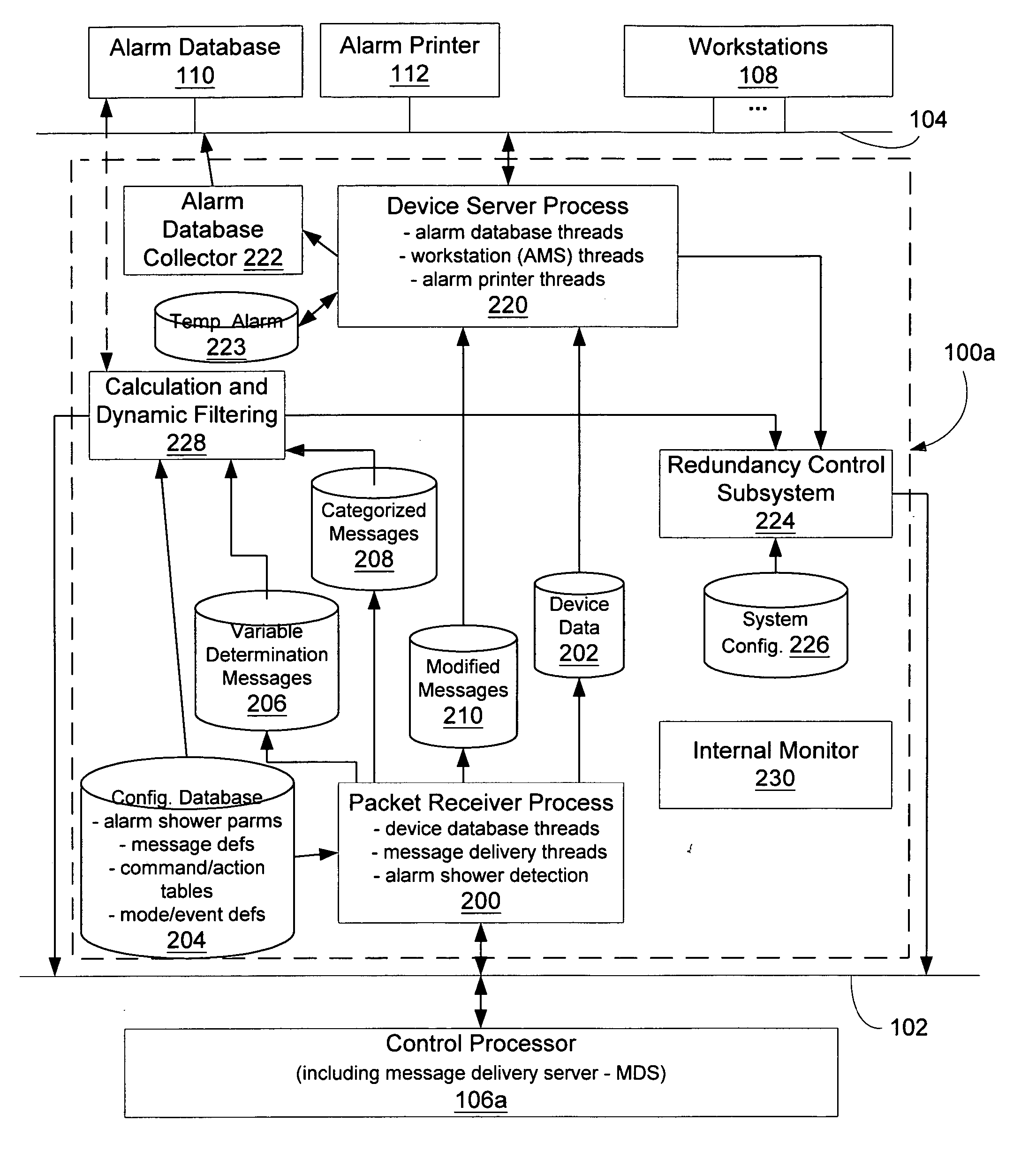
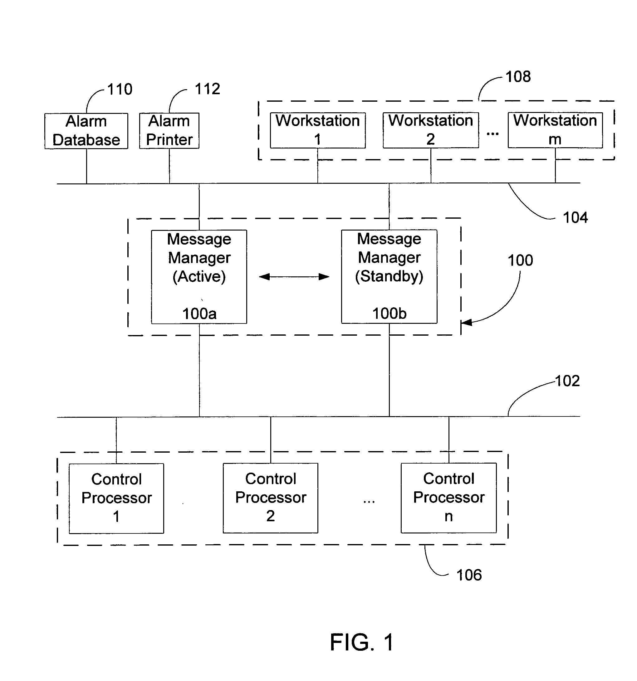
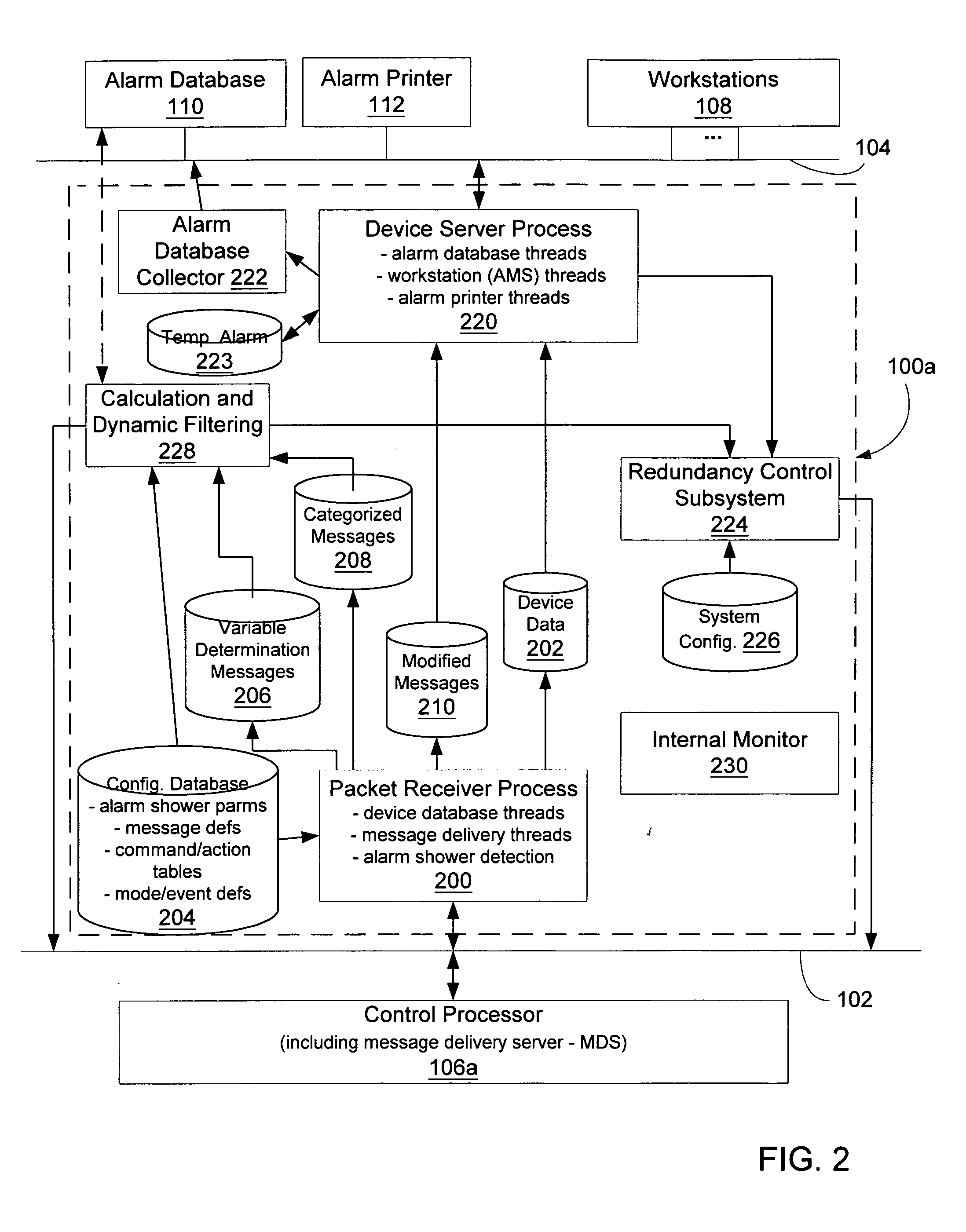
[0030] Structural and functional features of exemplary embodiments of the present invention are described herein with regard to configuration and runtime aspects of a message management facility. At runtime, the functionality of transmitting (“routing”) alarm messages, from control processors residing on a control network to one or more operator workstations (or other nodes) residing on an application network, has been extracted from the control processors and placed in one or more message management components executing on nodes coupled to a control network that hosts the control processors. The message management nodes are coupled to both the control network and the application network. Detecting and generating alarms takes place in the control processors (as before). Placing alarm routing functionality in a workstation or other node coupled to the application network reduces the computational and memory load on the control processor. Furthermore, placing routing functionality in ...


PUM


Abstract

A message management facility is described herein that is hosted by a networked node, in a process control network environment, that is separate from a control processor. The message management facility routes a stream of messages received from the control processor to a set of destinations on a supervisory network. By interposing the message management facility on a node that is interposed, in a message steam, between alarm message sources (control processors) and alarm message sinks (workstations, printers, historians), a number of additional functions can be implemented to carry out a number of advanced functions. Examples of such functions include: table-based routing of a single alarm to a number of destinations on an application network, suppressing alarm showers by applying a criterion to received messages when shower conditions have been sensed, invoking commands based upon a configured category assigned to particular identified messages prior to delivery of the message to its final destination, and invoking actions in response to event / mode status changes (including re-prioritizing alarms).

Description

FIELD OF THE INVENTION [0001] The present invention generally relates to the field of networked computerized process control systems. More particularly, the present invention relates to supervisory process control and manufacturing information systems. Such systems generally execute above a control layer in a process control system to provide guidance to lower level control elements such as, by way of example, programmable logic controllers. BACKGROUND [0002] Industry increasingly depends upon highly automated data acquisition and control systems to ensure that industrial processes are run efficiently, safely and reliably while lowering their overall production costs. Data acquisition begins when a number of sensors measure aspects of an industrial process and periodically report their measurements back to a data collection and control system. Such measurements come in a wide variety of forms. By way of example the measurements produced by a sensor / recorder include: a temperature, a...

Claims


Application Information

Patent Timeline
Patent Type & Authority Applications(United States)
IPC IPC(8): G06F15/16
CPCG05B19/4184G05B23/027G05B2219/31438G06F9/546H04L12/1895H04L45/00H04L43/08H04L67/02Y02P90/02H04L47/10
Inventor WILSON, IRVINE WILLIAMPAUL, MARKUS STEPHANWEISS, EWALD GERHARD
Owner INVENSYS SYST INC
Why Eureka
Try Eureka