
Resposable pulse oximetry sensor

a technology of pulse oximetry and disposable sensors, which is applied in the field of disposable (reusable/disposable) sensors, can solve the problems of deterioration of adhesive properties, tape eventually becoming soiled, and matter of minutes, and achieve the effect of long service life and associated cos

Inactive Publication Date: 2006-09-07
JPMORGAN CHASE BANK NA
View PDF99 Cites 37 Cited by
  • Summary
  • Abstract
  • Description
  • Claims
  • Application Information

AI Technical Summary

Benefits of technology

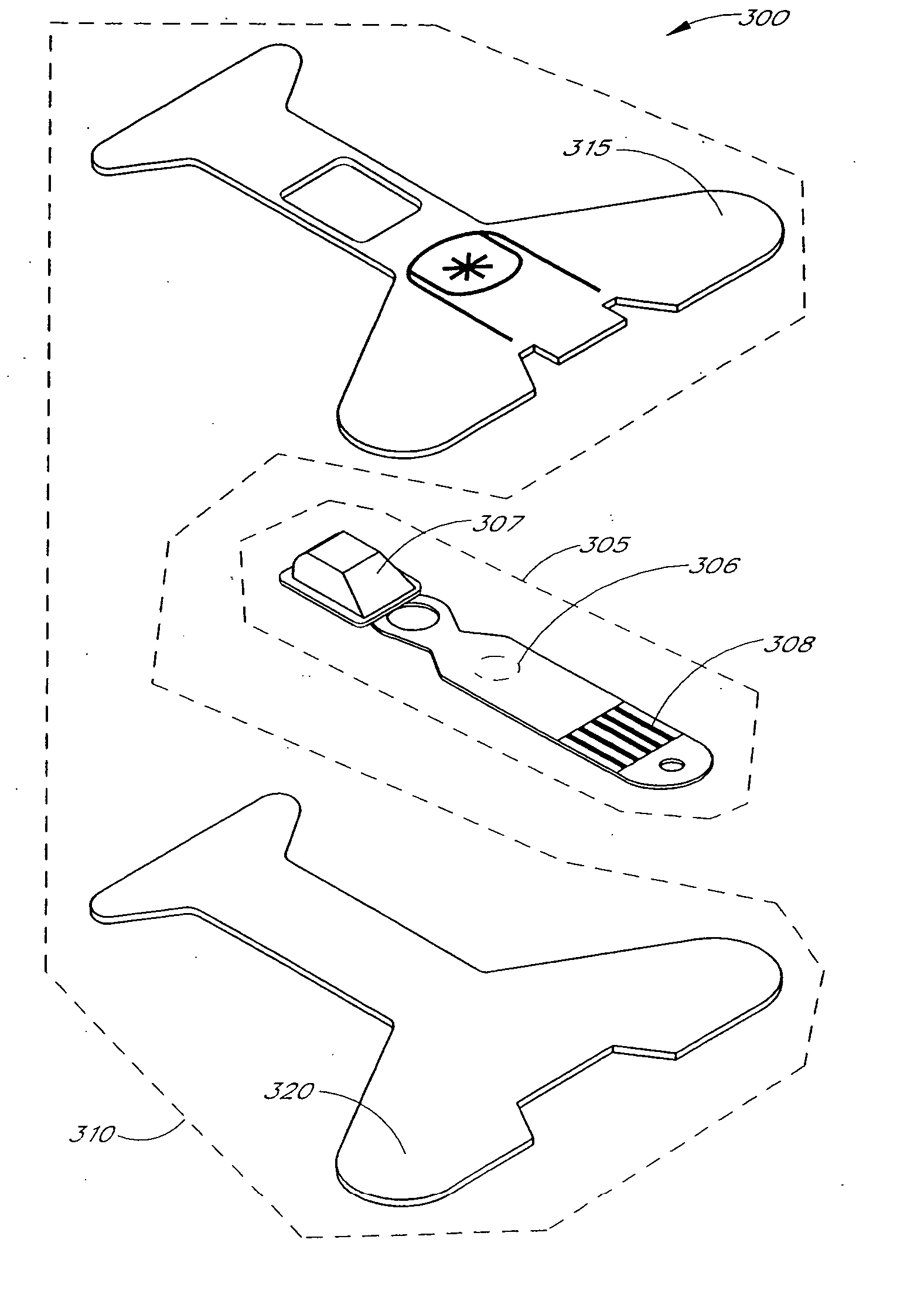
[0010] Accordingly, one aspect of the present invention is to provide a reusable / disposable (resposable) sensor having a disposable adhesive tape component that can be removed from other reusable sensor components. This hybrid sensor combines the longevity and associated cost advantages of the reusable sensor with the performance features of the disposable.

Problems solved by technology

For example, when a patient receives an insufficient supply of oxygen in critical care and surgical applications, brain damage and death can result in just a matter of minutes.
However, repeated removal and reattachment of the adhesive tape results in deterioration of the adhesive properties and tearing of the tape.
Further, the tape eventually becomes soiled and is a potential source of cross-patient contamination.
However, as mentioned above, the clip-type reusable sensor does not conform as easily to differing patient skin shape, resulting in diminished sensitivity and increased ambient light.
On the other hand, the circuit-type reusable sensor fails to provide quality control over the attachment mechanism.
Much like the disposable sensors, the attachment mechanism for the circuit-type reusable sensor may become soiled or damaged, thereby leading to cross-patient contamination or improper attachment.
Moreover, because the reusable circuit is severable from the attachment mechanism, operators are free to use attachment mechanisms that are either unsafe or improper with regard to a particular type of reusable circuitry.
Based on the foregoing, significant and costly drawbacks exist in conventional disposable and reusable oximetry sensors.

Method used


Image

  • Resposable pulse oximetry sensor
  • Resposable pulse oximetry sensor
  • Resposable pulse oximetry sensor

Examples


Embodiment Construction

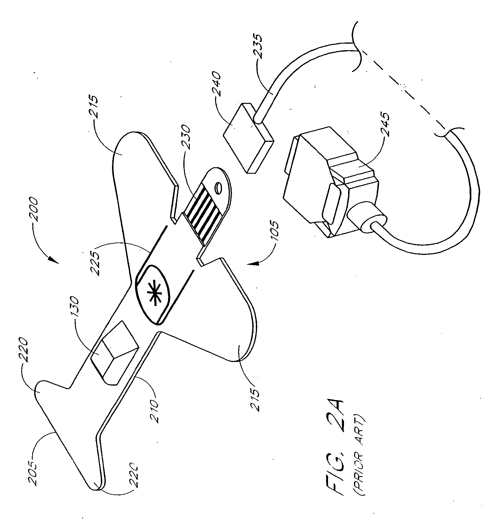
[0035] The configuration of an information element for an oximeter sensor and method of reading an information element with an attached oximeter is described in U.S. Pat. No. 5,758,644, assigned to the assignee of the current application, and incorporated by reference herein. Accordingly, the configuration and the implementation of an information element will be greatly summarized as follows.

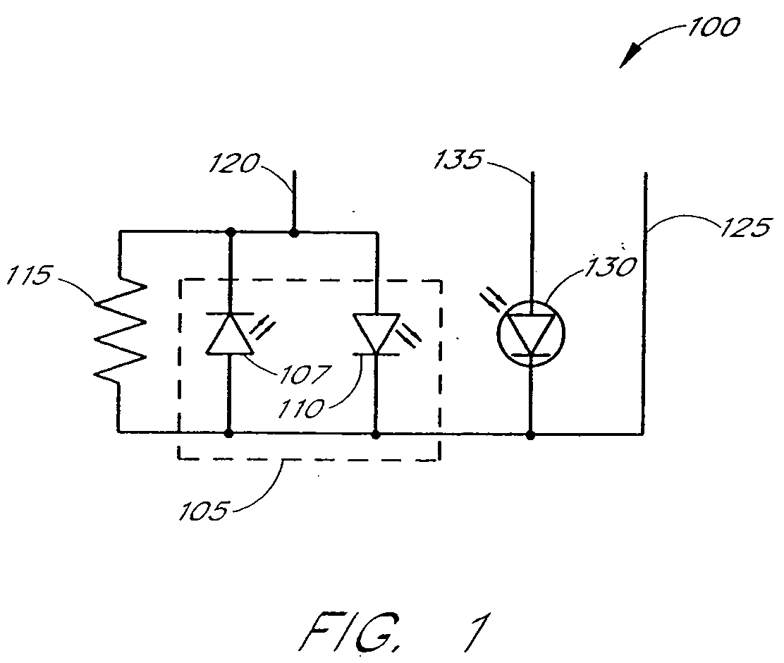
[0036]FIG. 1 illustrates a conventional oximeter sensor circuit 100. The oximeter sensor circuit 100 includes an emitter 105 comprising a first LED 107 and a second LED 110. The oximeter sensor circuit further includes an information element comprising a resistor 115. The first LED 107, the second LED 110 and the resistor 115 are connected in parallel. The parallel connection has a common input electrical connection 120 and a common return 125. The oximeter sensor circuit 100 also includes a photodetector 130 having an input electrical connection 135 connected to one end and having the common r...


PUM


Abstract

A pulse oximeter sensor has both a reusable and a disposable portion. The reusable portion of the sensor preserves the relatively long-lived and costly emitter, detector and connector components. The disposable portion of the sensor is the relatively inexpensive adhesive tape component that is used to secure the sensor to a measurement site, typically a patient's finger or toe. The disposable portion of the sensor is removably attached to the reusable portion in a manner that allows the disposable portion to be readily replaced when the adhesive is expended or the tape becomes soiled or excessively worn. The disposable portion may also contain an information element useful for sensor identification or for security purposes to insure patient safety.

Description

PRIORITY CLAIM TO RELATED APPLICATIONS [0001] The present application is a continuation of U.S. patent application Ser. No. 10 / 741,777, filed on Dec. 19, 2003, entitled “Resposable Pulse Oximetry Sensor,” now U.S. Pat. No. 7,039,449, which is a continuation of U.S. patent application Ser. No. 10 / 128,721, filed on Apr. 23, 2002, entitled “Resposable Pulse Oximetry Sensor,” which is a continuation of U.S. Patent No. U.S. patent application Ser. No. 09 / 456,666, filed Dec. 12, 1999, entitled “Resposable Pulse Oximetry Sensor,” now U.S. Pat. No. 6,377,829. The present application incorporates the foregoing disclosures herein by reference.FIELD OF THE INVENTION [0002] The present invention relates in general to sensors for measuring oxygen content in the blood, and, in particular, relates to resposable (reusable / disposable) sensors having an information element contained therein. BACKGROUND [0003] Early detection of low blood oxygen is critical in a wide variety of medical applications. F...

Claims


Application Information

Patent Timeline
Patent Type & Authority Applications(United States)
IPC IPC(8): A61B5/00A61B5/1455A61B5/145
CPCA61B5/14552A61B5/6826A61B5/6838Y10T137/4478
Inventor AL-ALI, AMMAR
Owner JPMORGAN CHASE BANK NA
Learn More