Externally adjustable endovascular graft implant

a graft and adjustable technology, applied in the field of abdominal aortic aneurysm treatment systems, methods and devices, can solve the problems of untreated lesion expansion and rupture, and the failure to achieve good sealing at the attachment site, so as to improve performance and reduce leakage

a graft and adjustable technology, applied in the field of abdominal aortic aneurysm treatment systems, methods and devices, can solve the problems of untreated lesion expansion and rupture, and the failure to achieve good sealing at the attachment site, so as to improve performance and reduce leakage

US20060212113A1Inactive Publication Date: 2006-09-21MICARDIA CORP

Image

  • Externally adjustable endovascular graft implant
  • Externally adjustable endovascular graft implant
  • Externally adjustable endovascular graft implant

Examples


Embodiment Construction

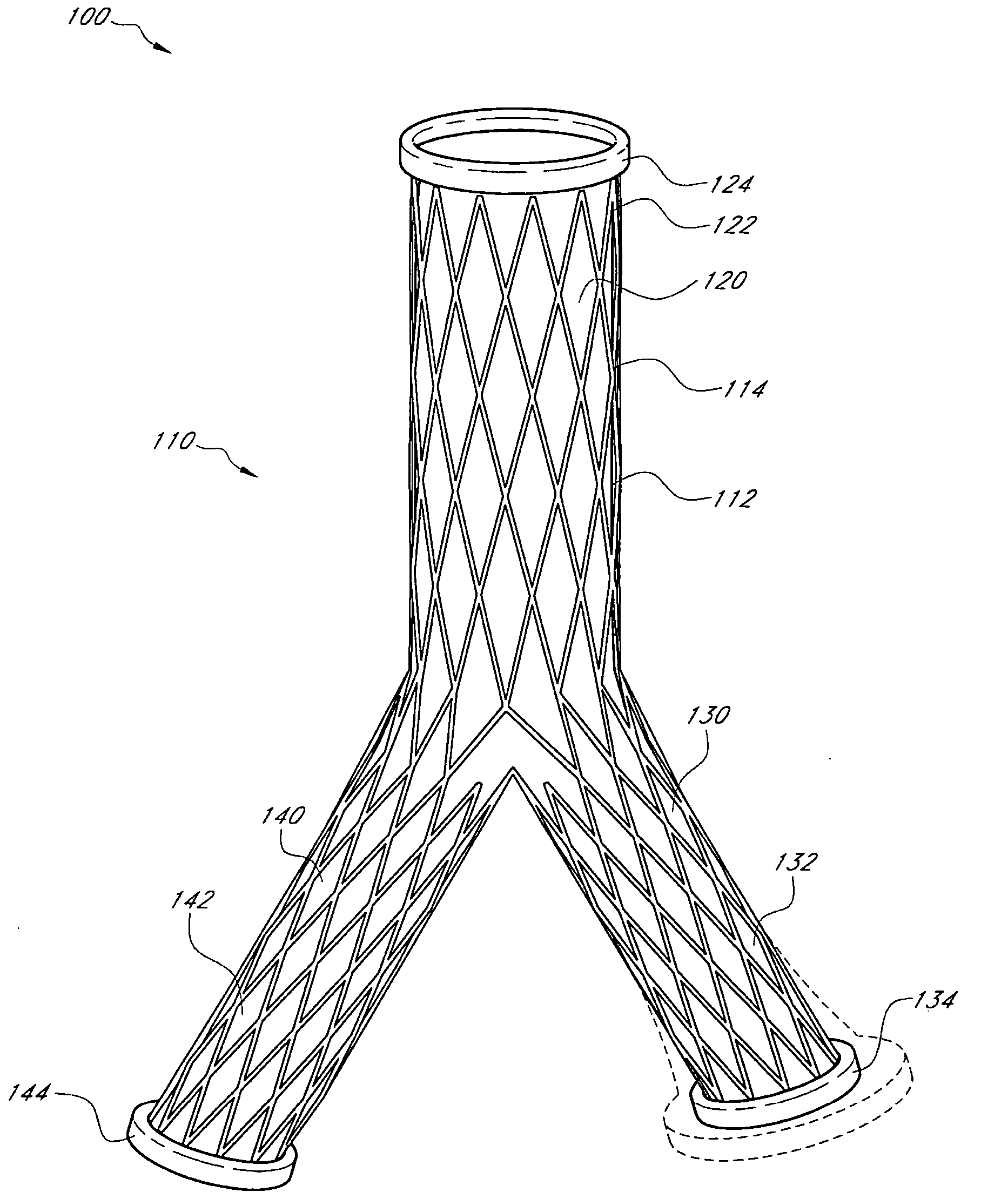
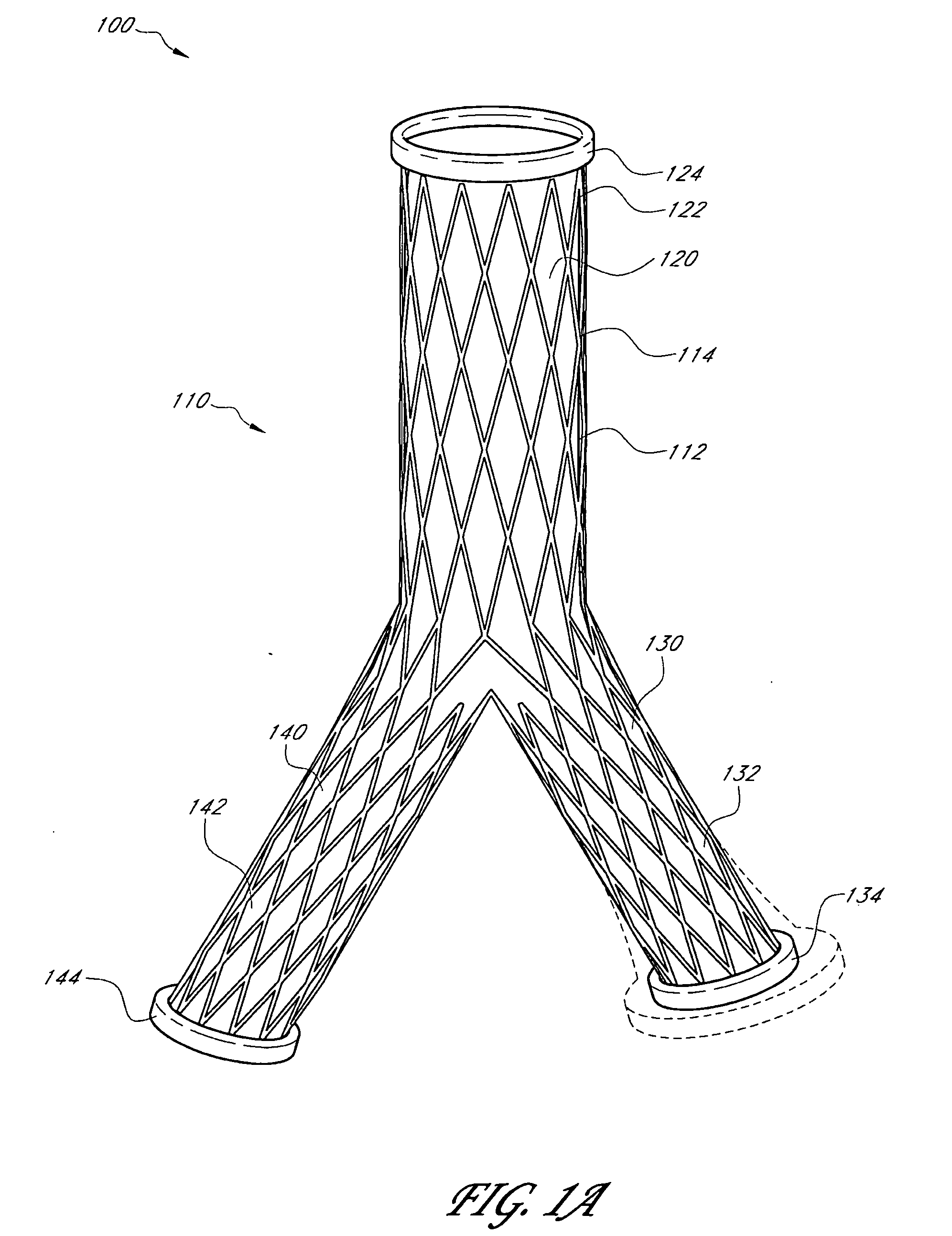
[0048] Systems, methods, and devices for reducing the shortcoming of current therapies, for example, endoleaks, use adjustable endovascular graft implants that are dynamically adjusted postoperatively using external energy sources. In some embodiments, the size and shape of the adjustable endovascular graft implant is adjustable to improve physiological performance based on the individual needs of each patient. The externally adjustable implants are also disclosed, for example, in U.S. Patent Publication Nos. 2006 / 0015178 A1, 2005 / 0288779 A1, 2005 / 0288777 A, 2005 / 0288783 A1, 2005 / 0288781 A1, 2005 / 0288782 A1, 2005 / 0288776 A1, 2005 / 0288778 A1, 2005 / 0288780 A1; and U.S. patent application Ser. Nos. 11 / 111,682, 11 / 123,874, 11 / 351,788, 60 / 656,451, the disclosures of which are incorporated by reference in their entireties.

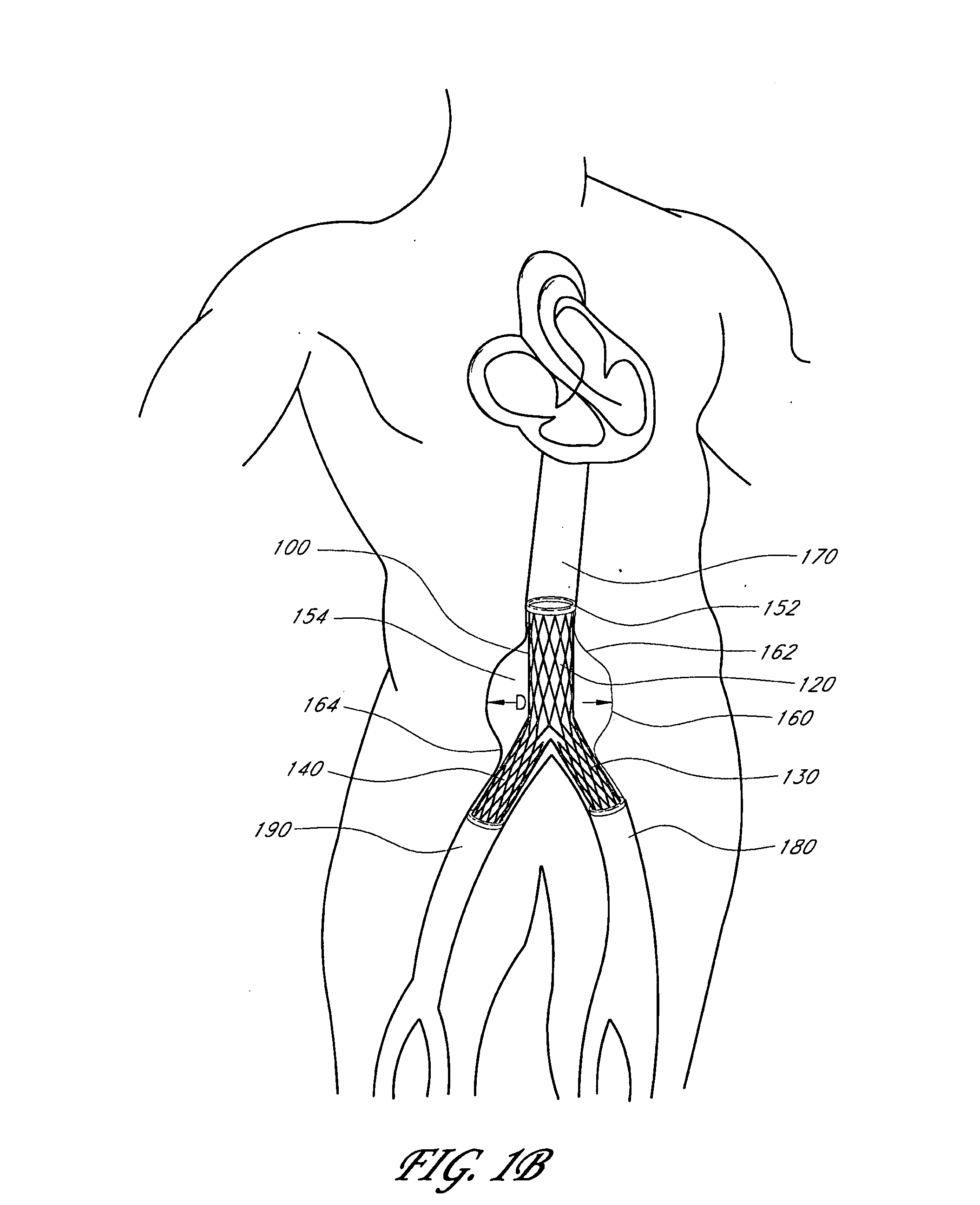
[0049] In some embodiments, an adjustable endovascular graft implant is implanted into the body of a patient such as a human or other animal. The adjustable endovascula...


PUM


Abstract

A device, method, and system for treating abdominal aortic aneurysms is described, where the device is an endovascular graft implant that one or more adjustable elements. The adjustable elements provide improved performance, for example, reduced leaking. The adjustable elements are adjustable within the body of a patient in a minimally invasive or non-invasive manner such as by applying energy percutaneously or external to the patient's body. Examples of suitable types of energy include, for example, acoustic energy, radio frequency energy, light energy, and magnetic energy.

Description

RELATED APPLICATIONS [0001] This application claims the benefit of U.S. Provisional Application No. 60 / 656,073, filed Feb. 24, 2005, the disclosure of which is incorporated by reference.BACKGROUND OF THE INVENTION [0002] 1. Field of the Invention [0003] The present application relates generally to systems, methods, and devices for treating abdominal aortic aneurysms. More specifically, the present application provides an externally adjustable endovascular graft implant. [0004] 2. Description of the Related Art [0005] An abdominal aortic aneurysm (AAA) is a bulging or ballooning out in the wall of the abdominal aorta. This large artery carries oxygen-rich blood from the heart to the lower portion of the body. [0006] An “aneurysm” is defined as a localized dilation of an artery by at least 50% as compared with the expected normal diameter of the vessel. The term “ectasia” is used when the dilation is less than 50%. If the arteries are diffusely enlarged by 50% or more, the condition i...

Claims


Application Information

Patent Timeline
21 Sep 2006
Publication
US20060212113A1
IPC
A61F2/06
CPC
A61F2/07; A61F2002/065; A61F2250/0001; A61F2250/0065; A61F2250/0069; A61F2/90; A61F2002/072; A61F2250/001
Inventors
SHAOLIAN, SAMUEL M.; SHAOULIAN, EMANUEL