Fuel cell system and mobile communication device including the same

a fuel cell and mobile communication technology, applied in the field of fuel cell and electronic devices, can solve the problems of insufficient battery life of secondary batteries, difficult to quickly remove heat generated by devices, and difficult to supply oxygen when the device is being used, so as to reduce thickness and volume

Inactive Publication Date: 2006-11-23
SAMSUNG SDI CO LTD
View PDF8 Cites 14 Cited by
  • Summary
  • Abstract
  • Description
  • Claims
  • Application Information

AI Technical Summary

Benefits of technology

[0011] Aspects of the present invention provide a fuel cell system that can supply air and discharge gas (CO2) freely. The fuel cell system has a fuel cell with a reduced thickness and volume, and replacing of a fuel tank and supplying of fuel can be performed in a simple way.
[0025] According to the present invention, since the fuel cell system is constructed using the idle area of the communication device, that is, an area of the communication device that is not used for electronics, etc., an increase in the thickness and volume of the communication device due to the fuel cell system can be minimized. In addition, the idle area, such as, for example, an upper rear portion of the upper panel in a sliding type cellular phone, is exposed to the atmosphere. In the communication device of the present invention, a path for inducing and discharging gas, such as, for example, a hole, may be formed on the idle area. Therefore, according to the present invention, the air can be induced freely, and gas generated during the operation of fuel cell system, such as, for example, carbon dioxide, can be discharged freely. In addition, the heat generated when the fuel cell is used can be discharged rapidly.

Problems solved by technology

Thus, in actual usage conditions, the battery life of the secondary battery is not long enough when operating time, in particular, communicating time, takes up a larger part of the battery's use.
However, since the back side of the device is generally covered by the hand of a user, it may be difficult to supply the oxygen when the device is being used.
Moreover, it may be difficult to rapidly remove heat generated by the device, and to discharge generated CO2.
Moreover, when the fuel tank is located behind a cell pack, it may be difficult to replace the fuel tank or supply the fuel.

Method used


Image

  • Fuel cell system and mobile communication device including the same
  • Fuel cell system and mobile communication device including the same
  • Fuel cell system and mobile communication device including the same

Examples


Embodiment Construction

[0056] Reference will now be made in detail to the present embodiments of the present invention, examples of which are illustrated in the accompanying drawings, wherein like reference numerals refer to the like elements throughout. The embodiments are described below in order to explain the present invention by referring to the figures.

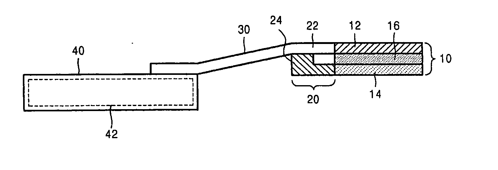
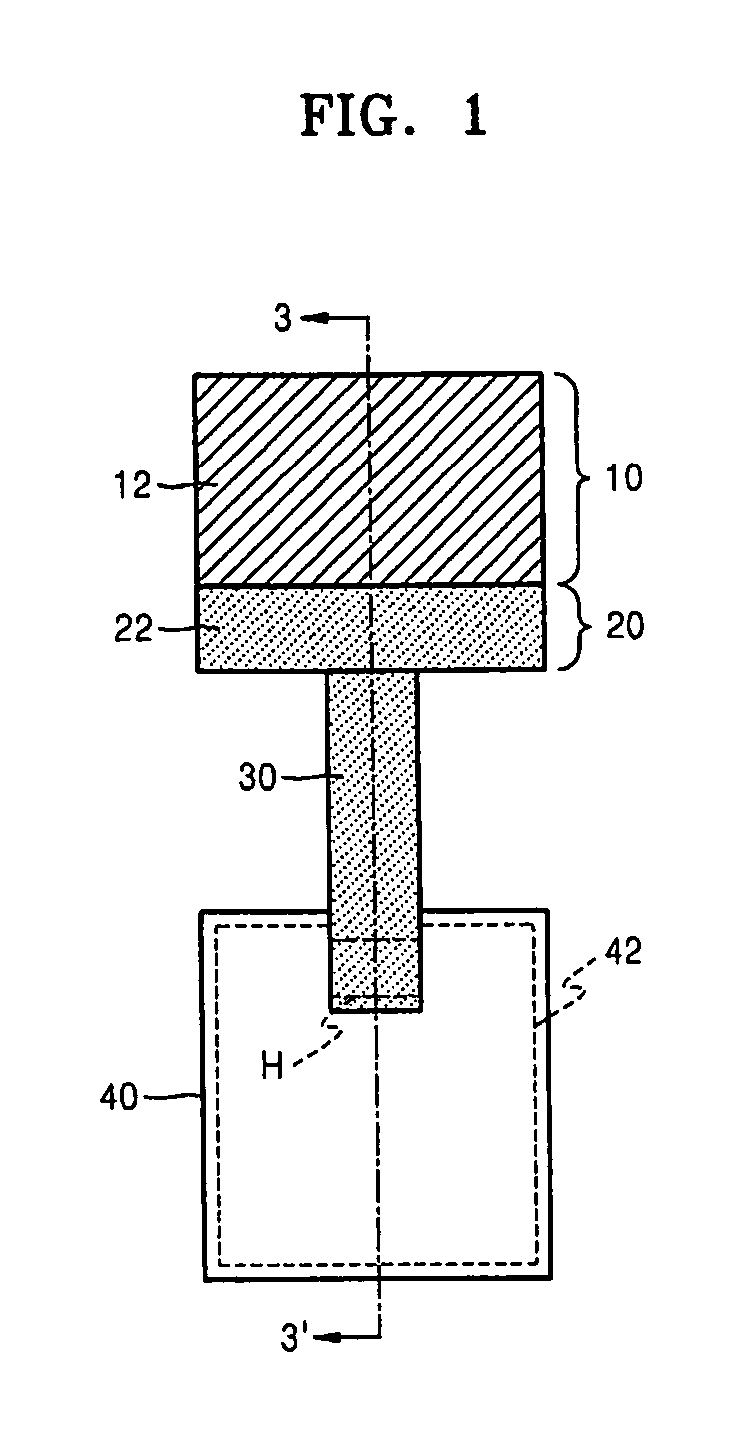
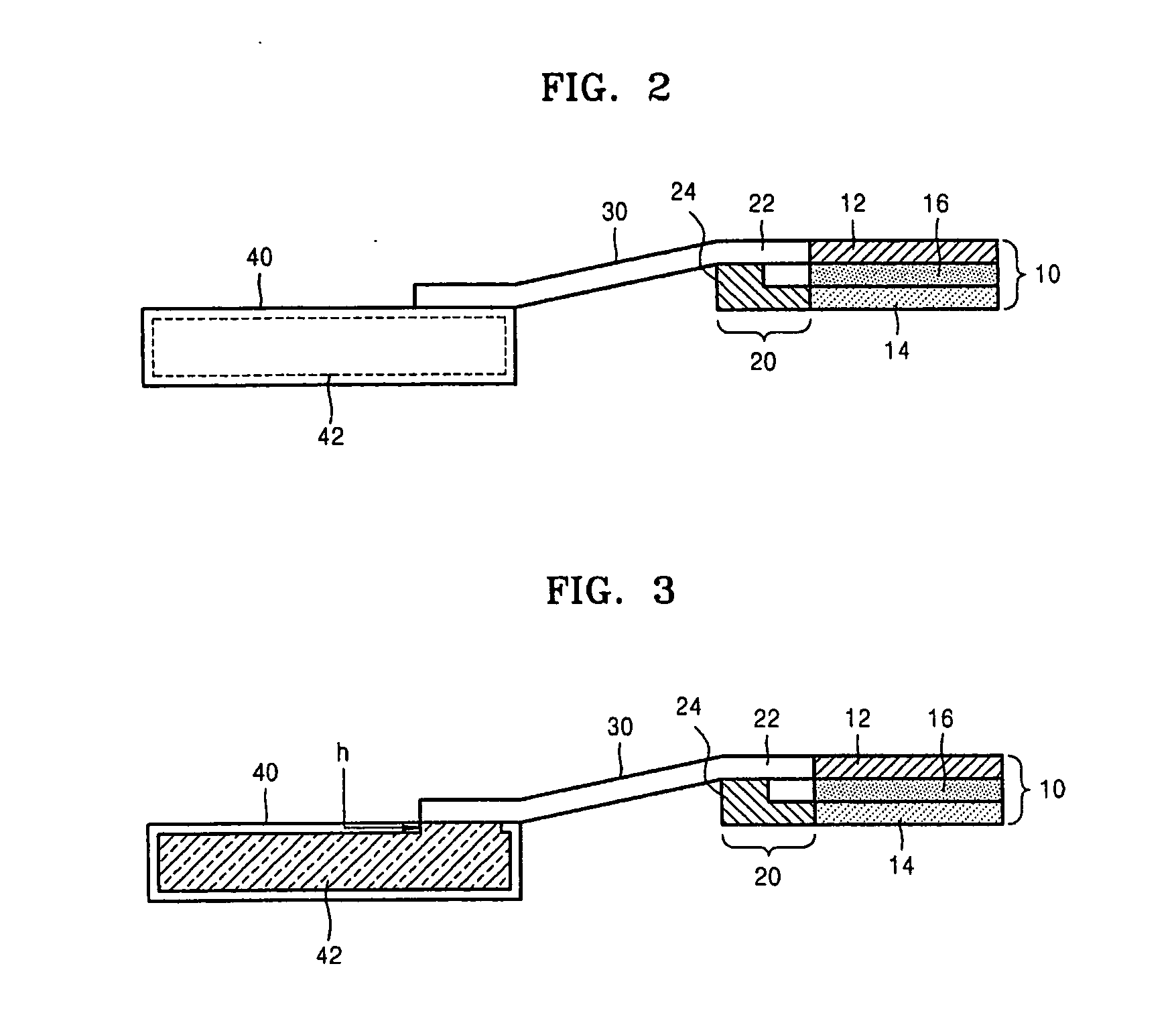
[0057] A fuel cell system and a mobile communication device including the fuel cell system according to aspects of the present invention will now be described more fully with reference to the accompanying drawings, in which exemplary embodiments of the invention are shown. In the drawings, the thicknesses of layers and regions are exaggerated for clarity. As used herein, the terms “front,”“rear,”“upper,”“lower,”“under,” etc., are used in their ordinary understood meanings to describe the fuel cell system and mobile communication device from the perspective of a user of the devices. For example, the front of a mobile communication device refers to the...


PUM

PropertyMeasurementUnit
capillary forceaaaaaaaaaa
weightaaaaaaaaaa
sizeaaaaaaaaaa

Abstract

A fuel cell system includes: a cell pack including an anode layer, a cathode layer, and an electrolyte; a fuel tank separated from the cell pack, and having a hole; a fuel mixture unit connected to the cell pack; a fuel storage medium included in the fuel tank, and a part of which is exposed through the hole; and a fuel supplying path having a first end connected to the fuel mixture unit, and a second end connected to the fuel storage medium only when the fuel cell system operates. A mobile communication device includes the fuel cell system.

Description

CROSS-REFERENCE TO RELATED APPLICATIONS [0001] This application claims the benefit of Korean Application No. 2005-41285, filed May 17, 2005, in the Korean Intellectual Property Office, the disclosure of which is incorporated herein by reference. BACKGROUND OF THE INVENTION [0002] 1. Field of the Invention [0003] Aspects of the present invention relate to a fuel cell and an electronic device including the fuel cell, and more particularly, to a fuel cell system and a mobile communication device including the fuel cell system. [0004] 2. Description of the Related Art [0005] As Internet technologies have been continuously developed, the number of Internet users has increased, and wireless mobile communication devices have been used more frequently. Naturally, batteries with light weight, small size, and large capacity have been required for such devices. Accordingly, secondary batteries having light weight and long battery life have been desired. However, the battery life of the seconda...

Claims


Application Information

Patent Timeline
Patent Type & Authority Applications(United States)
IPC IPC(8): H01M8/02H01M8/04H04B1/38H01M8/04186H04M1/02
CPCH01M8/04186H01M8/04201Y02E60/50H01M8/1011H01M8/04216H04M1/0262
Inventor LEE, JAE-YONGOH, JUNG-MIN
Owner SAMSUNG SDI CO LTD
Why Eureka
Try Eureka