Power transfer unit

a technology of power transfer unit and power transfer unit, which is applied in the direction of gearing details, gearing, transportation and packaging, etc., can solve the problems of limiting the size of the power transfer unit, reducing the size of these components, and limiting the overall torque carrying capacity, so as to achieve more laterally compact construction

Active Publication Date: 2007-01-11
FORD MOTOR CO +1
View PDF16 Cites 18 Cited by
  • Summary
  • Abstract
  • Description
  • Claims
  • Application Information

AI Technical Summary

Benefits of technology

[0018] In each embodiment the outer surface of the idler shaft has a constant outside diameter, which facilitates assembly and installation in the housing. In one embodiment the idler gear can be formed from tube stock at low cost and requires little machining.
[0021] By providing the support for the idler gear through a non-rotating idler shaft, bearing supports for that idler shaft are eliminated. By eliminating these bearing supports, additional area within the power transfer unit is freed up so as to accommodate the ring gear of the non-parallel gear set in a more laterally compact construction. In other words, the ring gear of the non-parallel gear set need not be laterally staggered or spaced so as to avoid conflict with the bearing support for the idler gear.

Problems solved by technology

The proximity to the engine, transmission and the other under hood components accordingly limits the size of the power transfer unit.
However, reducing the size of these components limits their overall torque carrying capacity.
This can result in conflicts in the sizing and shaping of various components of the unit.
For example, in a three axis power transfer unit, a conflict can exist between the sizing of a hypoid ring gear and clearance between that ring gear and the support shaft of an idler gear.
Because of the size of the ring gear typically required in power transfer units and because of the size of the bearings required to support the shaft upon which the idler gear is mounted, the ring gear and the idler gear bearing support are too large and located too longitudinally close together to enable these components to be mounted in a common plane.
Even then, the size of the ring gear encroaches on the idler gear support shaft thereby limiting the size of that shaft.
Clearly, merely reducing the cross-sectional diameter of the idler gear support shaft would result in reduced strength in the shaft and thereby limiting the size and capacity of the shaft, as well as the supporting bearing.

Method used


Image

  • Power transfer unit
  • Power transfer unit
  • Power transfer unit

Examples


Embodiment Construction

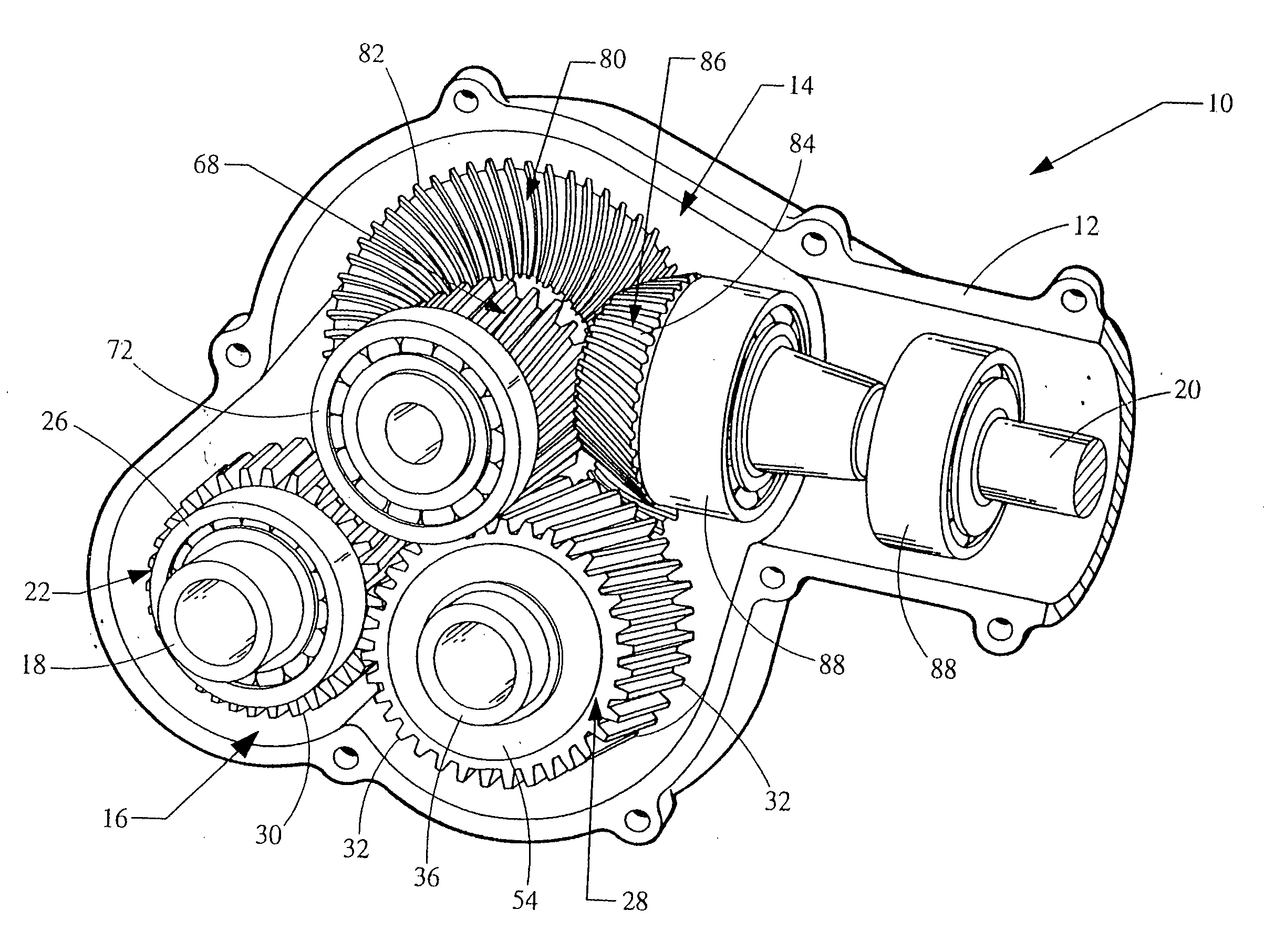
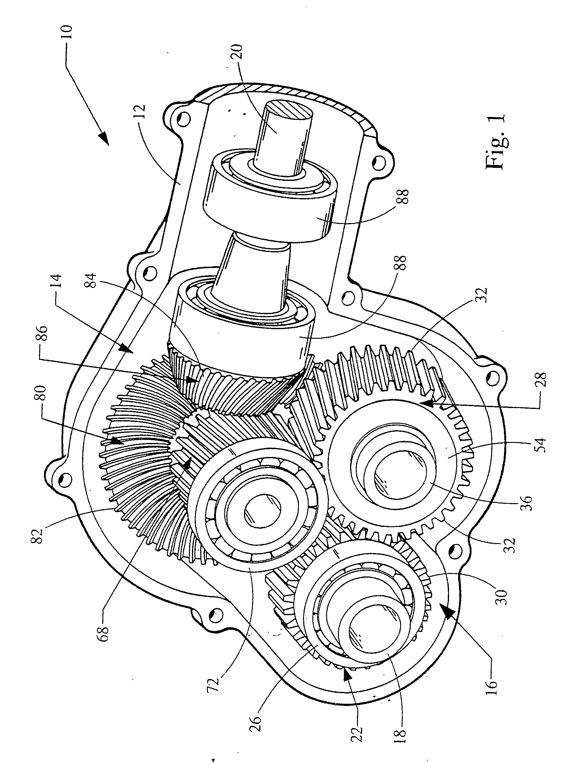
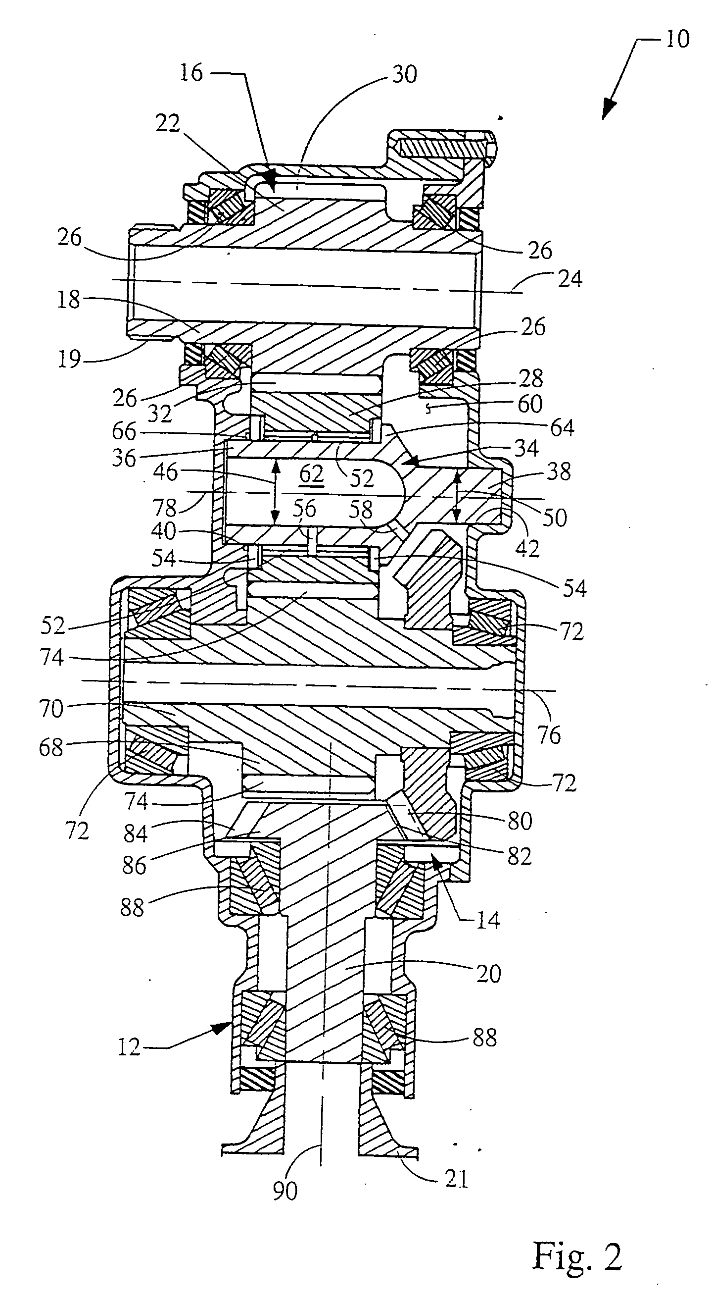
[0031] Referring now to the drawings, FIG. 1 illustrates a power transfer unit 10 incorporating the principles of the present invention. The power transfer unit 10 includes a housing 12 in which the primary components of the unit 10 are integrally packaged. These components principally include a non-parallel gear set 14 and a parallel gear set 16.

[0032] As used herein, the term “parallel gear set” is intended to refer to mechanisms with gear wheels that transfer power from a first shaft to a second shaft; the first and second shafts defining axes that are generally parallel to one another.

[0033] The term “non-parallel gear set”, as used herein, is intended to refer to any mechanism, (including, without limitation, mechanisms with gear wheels, mechanisms without gear wheels, gear trains, chain gears and belt systems) for transferring power from a first shaft to a second shaft; wherein the first and second shafts define axes that are generally not parallel to one another.

[0034] As ...


PUM


Abstract

A motor vehicle power transfer unit for distributing torque from a transmission assembly between a front wheel drive line and a rear wheel drive line, said power transfer unit includes a housing, non-parallel gear set located in the housing and including a ring gear, and a parallel gear set including an idler, and an idler shaft secured to and supported on the housing. The idler shaft, which extends through the idler gear and supports the idler gear for rotation, includes an interior chamber, an outer surface, and a wall. A portion of the outer surface is formed with a clearance space, into which space a portion of the ring gear extends and rotates. The clearance space communicates through the wall to the chamber, the wall being formed with a hydraulic passage, which carries lubricant from the chamber to the outer surface.

Description

CROSS-REFERENCE TO RELATED APPLICATION [0001] This application is a continuation-in-part of the co-pending U.S. patent application Ser. No. 10 / 444,032, filed May 22, 2003.BACKGROUND OF THE INVENTION [0002] 1. Field of the Invention [0003] The present invention relates to the power train of a motor vehicle. More specifically, the present invention relates to a power transfer unit for distributing power to the wheels of the vehicle. [0004] 2. Description of the Prior Art [0005] Most automobiles in the United States have typically utilized a rear wheel drive power delivery scheme. In adapting these rear wheel drive schemes into four wheel drive applications, a transfer case was, and often still is, positioned at the output of the transmission assembly. When engaged, the transfer case diverts a portion of the power coming from the transmission assembly from the rear wheels to the front wheels. [0006] Currently in the United States, a significant portion of new automobiles are front whee...

Claims


Application Information

Patent Timeline
Patent Type & Authority Applications(United States)
IPC IPC(8): F16H1/14B60K17/344F16H1/08F16H1/20F16H48/06F16H57/021
CPCB60K17/344F16H1/06F16H1/08F16H1/14F16H1/20F16H1/203Y10T74/19093F16H2057/02086Y10T74/19647Y10T74/19674Y10T74/19693Y10T74/19107F16H57/021
Inventor MARLA, DURGAPRASADADLER, JONATHANCOOK, DENNISMONKABA, GARY
Owner FORD MOTOR CO
Why Eureka
Try Eureka