
Water Valve Apparatus

a technology of water valves and water valves, applied in the direction of liquid transfer devices, furnaces, manufacturing tools, etc., can solve the problems of inability to completely stop the flow, easy malfunction, and high cost of infrared ray sensors, so as to simplify the entire structure of the water valve and increase the life of the valv

Inactive Publication Date: 2010-03-04
LIAO HUI FEN
View PDF15 Cites 3 Cited by
  • Summary
  • Abstract
  • Description
  • Claims
  • Application Information

AI Technical Summary

Benefits of technology

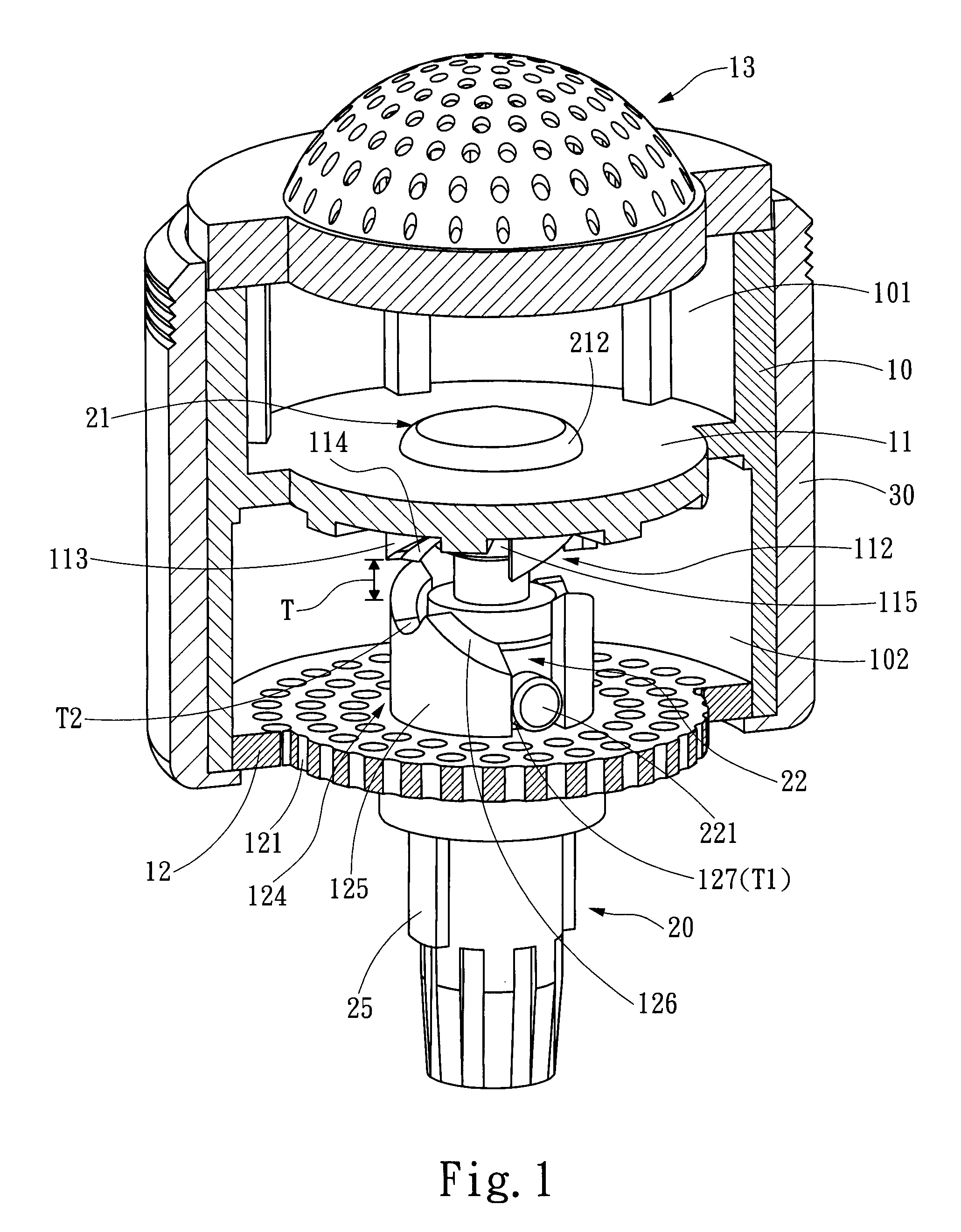
[0005]The primary object of the present invention is to simplify the entire structure of a water valve and increase its life span. To achieve the foregoing object the water valve apparatus according to the invention includes a housing and a control valve stem. The housing has a spacer to divide the interior space thereof into a first chamber and a second chamber, and a base located at the bottom of the housing with a plurality of water outlets formed thereon. The spacer has a first opening communicating with the first chamber and the second chamber. The base has a second opening corresponding to the first opening. The spacer and the base have respectively a first track portion and a second track portion opposing each other. There is a displacement track between the first track portion and the second track portion. The displacement track has at least a first anchor zone and a second anchor zone. The control valve stem runs through the first opening and second opening, and has a water stopper located in the first opening to stop communication of the first chamber and second chamber, and an anchor ring movably coupled on the control valve stem. The anchor ring has at least one anchor stub in the displacement track. Through the anchor stub anchor ring can move to the first anchor zone or second anchor zone to drive the control valve stem at a water supply position with the first and second chambers communicating with each other, or a water stop position with the first and second chambers not communicating with each other.
[0006]The water stopper has a bulged portion to withstand water pressure and closely seal the first opening to stop water from passing through. To provide filtering effect for the water valve apparatus a filter unit is provided in the first chamber. To facilitate assembly and installation, the anchor ring is a C-shaped ring. The base and housing are separated elements. The base and housing have respectively a first coupling portion and a second coupling portion corresponding to each other.
[0010]1. Simpler structure, and can be fabricated and assembled easily to reduce production cost.
[0011]2. The water stopper can closely seal the first opening through water pressure, thus there is no need to add an extra spring to enhance the sealing between the water stopper and the first opening.
[0012]3. As the anchor ring is movably coupled on the control valve stem, and the control valve stem and the base have respectively the retaining member and retaining track corresponding to each other, the control valve stem can be moved in the direction of the retaining track to reduce wearing of related elements to increase the life span of the apparatus.

Problems solved by technology

When the turning angle or force is insufficient water flow cannot be completely stopped.
Waste of water resource occurs.
But the infrared ray sensor is expensive and easily malfunctions.
It is not always economically justified.
However, to stop water flow could be difficult sometimes due to not proper positioning of the angle of the operating lever and result in waste of water resource.
But the spring could suffer from elastic fatigue and fail to maintain a desired sealing condition.
However, their structures are complicated and difficult to produce and assemble, thus lack desired stability.

Method used


Image

  • Water Valve Apparatus
  • Water Valve Apparatus
  • Water Valve Apparatus

Examples


Embodiment Construction

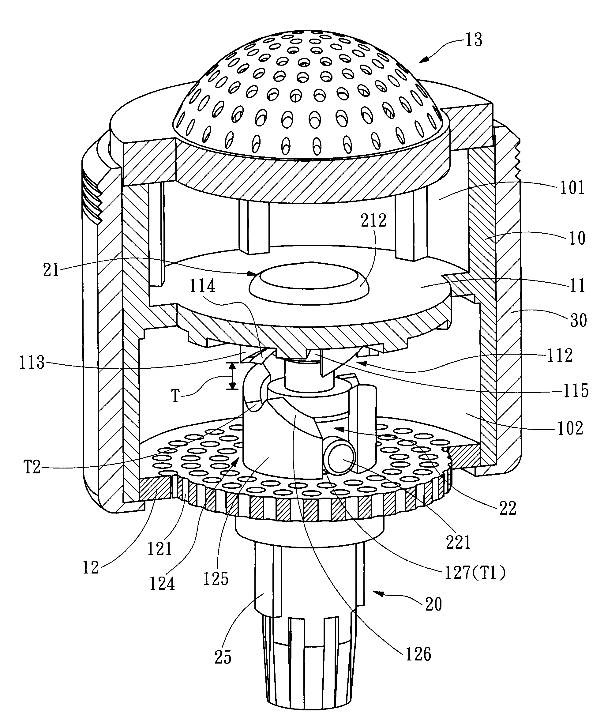
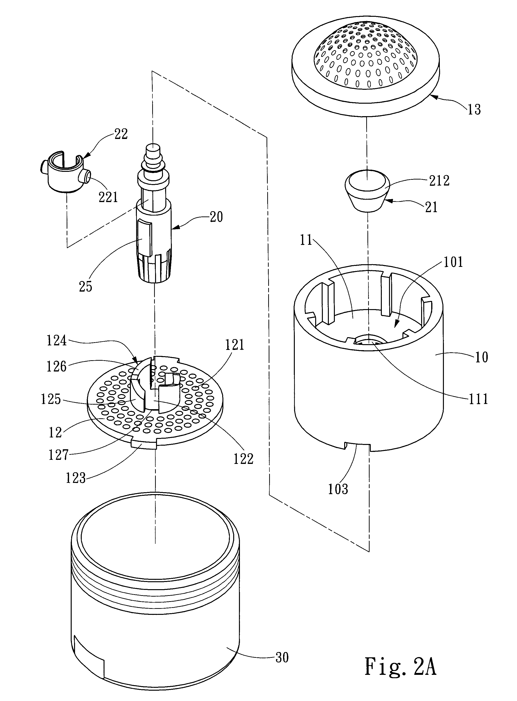
[0018]Please refer to FIGS. 1 through 3 for a preferred embodiment of water valve apparatus of the invention adopted for use on a faucet. It includes a housing 10 and a control valve stem 20. The housing 10 has a spacer 11 to divide the interior space into a first chamber 101 and a second chamber 102, and a base 12 located at the bottom of the housing 10 with a plurality of water outlets 121 formed thereon. The spacer 11 has a first opening 111 communicating with the first chamber 101 and the second chamber 102. The base 12 has a second opening 122 corresponding to the first opening 111. The base 12 and the housing 10 are separated elements, and have respectively a first coupling portion 123 and a second coupling portion 103 corresponding to each other to allow the base 12 to be fastened on the bottom of the housing 10. In this embodiment the housing 10 is further coupled with a cap 30 on an outer side to anchor on a water supply 40 such as a water pipe or water faucet. To provide f...


PUM

PropertyMeasurementUnit
turning angleaaaaaaaaaa
forceaaaaaaaaaa
areaaaaaaaaaaa

Abstract

A water valve apparatus includes a housing and a control valve stem. The housing has a spacer to divide the interior space and a base with a plurality of water outlets formed thereon. The spacer has a first opening. The base has a second opening corresponding to the first opening. The spacer and base are interposed by a displacement track. The displacement track has at least one first anchor zone and one second anchor zone. The valve control stem runs through the first opening and second opening, and has a water stopper located in the first opening and an anchor ring movably coupled thereon. The anchor ring has at least an anchor stub in the displacement track. The valve control stem is operable easily to allow users to determine water supply. No excessive contact with water faucets is needed. Thus the risk of bacteria contagion can be minimized.

Description

FIELD OF THE INVENTION[0001]The present invention relates to a water valve apparatus and particularly to water valve apparatus to provide simple control of water supply.BACKGROUND OF THE INVENTION[0002]The commonly seen water control apparatus now on the market mainly are mechanical water faucets. When in use they are opened and closed by turning to regulate water flow. When the turning angle or force is insufficient water flow cannot be completely stopped. Waste of water resource occurs.[0003]There is another conventional method to control water flow through infrared ray detection. By placing user's hands in an infrared ray detection area the faucet can be triggered to open or close. But the infrared ray sensor is expensive and easily malfunctions. It is not always economically justified.[0004]There are many other water valve control devices known in the art, such as U.S. Pat. Nos. 4,512,551 and 5,286,000. They mainly have an operating lever in the spout of a water faucet. The oper...

Claims


Application Information

Patent Timeline
Patent Type & Authority Applications(United States)
IPC IPC(8): F16K51/00
CPCE03C2001/026E03C1/08
Inventor LIAO, HUI-FEN
Owner LIAO HUI FEN
Learn More