Folding tent with central self-lock structure

a tent and self-locking technology, applied in tents/canopies, building types, constructions, etc., can solve the problems of high product processing cost, cumbersome operation, unsuitable for carrying out, etc., and achieve the effect of convenient processing, low cost and simple structur

Active Publication Date: 2021-05-04
ZHEJIANG JASAN LEISURE PROD
View PDF30 Cites 1 Cited by
  • Summary
  • Abstract
  • Description
  • Claims
  • Application Information

AI Technical Summary

Benefits of technology

[0005]For the above problems, the disclosure aims to provide a folding tent with central self-lock structure, which has advantages of simple structure, convenient processing, low cost and good stability.
[0017]In the disclosure, by optimization of the design, a plurality of self-lock unit structures are provided, especially the combination design of self-lock unit and lower disc assembly, so that the locking or unlocking of the lock rod assembly may be completed, which simplifies the structure of the self-lock unit and facilitates the assembly and installation of the self-lock unit. Furthermore, the structure design of the elastic member is preferred, so that the locking and the resetting property of the elastic member itself may be used to simplify the installation structure of the self-lock unit with the lock rod assembly, and to also achieve locking or unlocking of the lock rod assembly In summary, in the disclosure, by optimizing the structure of the self-lock unit, the product is facilitated in installation, the production cost is reduced and the product processing is facilitated.

Problems solved by technology

Due to a large size, the fixed-type tent is generally suitable for long-term fixed placement and is not suitable for carrying out.
However, the traditional folding tent usually has a locking buckle on the leg pole, and requires multiple people to complete the folding storage or deployment, which is cumbersome to operate.
However, this type of single-point lock structure is relatively complicated, and it needs to be integrated in the center tube, leading to higher product processing costs, and individual spare parts are prone to wear and tear during long-term use, resulting in improper use of the product and affecting performance.

Method used


Image

  • Folding tent with central self-lock structure
  • Folding tent with central self-lock structure
  • Folding tent with central self-lock structure

Examples


embodiment 1

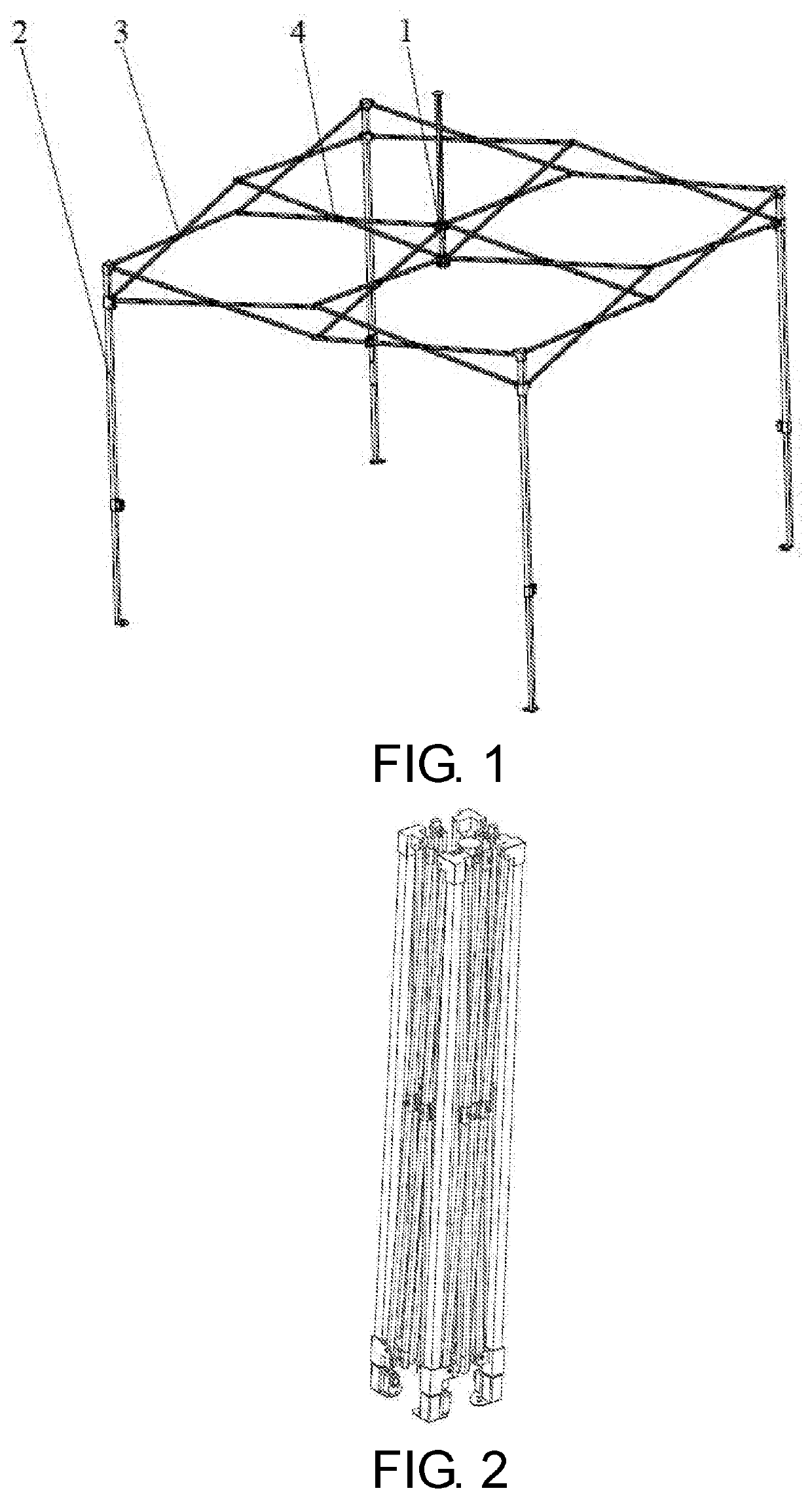
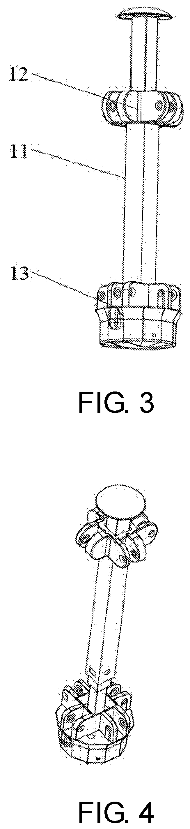
[0050]As shown in FIG. 1 and FIG. 2, the present disclosure provides a folding tent with central self-lock structure including a plurality of tent leg tubes 2, a plurality of side cross units 3, a plurality of middle cross units 4 and at least one central self-lock mechanism 1. The central self-lock mechanism 1 is configured to be installed in cooperation with one end of the middle cross units 4, and the central self-lock mechanism 1 comprises a lock rod assembly 11, a self-lock unit 14, an upper disc member 12 and a lower disc assembly 13. The lock rod assembly 11 is in a telescopic rod structure. When the folding tent is in an unfolded state, the self-lock unit 14 and the lock rod assembly 11 are locked, and a spacing between the upper disc member 12 and the lower disc assembly 13 is the smallest. When the folding tent is in a retracted state, the self-lock unit 14 and the lock rod assembly 11 are unlocked, the lock rod assembly 11 is telescopic, and the spacing between the upper ...

embodiment 2

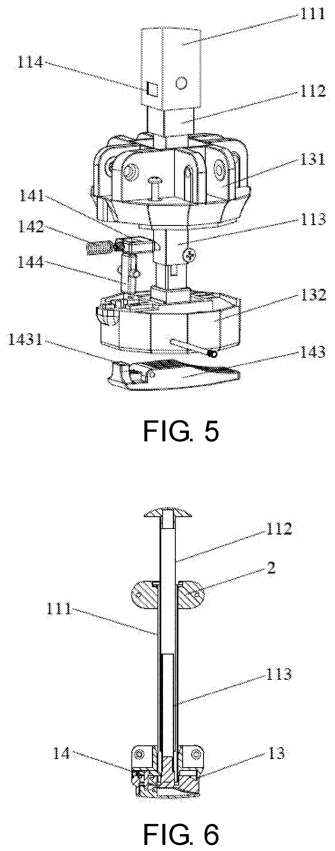
[0054]As shown, based on Embodiment 1, in the present embodiment, the self-lock unit 14 is configured to be mounted in cooperation with the lower disc assembly 13 to integrate the self-lock unit 14 and the lower disc assembly 13, so as to facilitate installation of the self-lock unit 14, and to simplify the structures of the self-lock unit 14 and the lock rod assembly 11 while facilitating the locking or unlocking of the lock rod assembly 11.

[0055]Among them, preferably, the self-lock unit 14 includes a lock tab 141, a return spring 142, a driving pin 144 and a trigger 143. The trigger 143 is hingedly engaged with the lower disc assembly 13, and one end of the trigger 143 is movable against the driving pin 144. An upper end of the driving pin 144 is engaged with the lock tab 141, and the return spring 142 is configured to act on the lock tab 141. The driving pin 144 is hingedly engaged with the lower disc assembly 13.

[0056]Among them, the lower disc assembly 13 includes a first lowe...

embodiment 3

[0059]As shown, based on Embodiment 1, in the present embodiment, the self-lock unit 14 is configured to be mounted in cooperation with the lower disc assembly 13 to integrate the self-lock unit 14 and the lower disc assembly 13, so as to facilitate installation of the self-lock unit 14, and to simplify the structures of the self-lock unit 14 and the lock rod assembly 11 while facilitating the locking or unlocking of the lock rod assembly 11.

[0060]Among them, preferably, the self-lock unit 14 includes the lock tab 141, the return spring 142 and a pressing plate 145. The trigger 145 is hingedly engaged with the lower disc assembly 13, and one end of the pressing plate 145 is movable against the lock tab 141. The return spring 142 is configured to act on the lock tab 141.

[0061]Among them, the lower disc assembly 13 includes the first lower disc 131 and the second lower disc 132, and the first lower disc 131 and the second lower disc 132 are assembled up and down with an inside formed ...


PUM


Abstract

A folding tent with central self-lock structure comprises a plurality of tent leg tubes, a plurality of side cross units, a plurality of middle cross units and at least one central self-lock mechanism. The central self-lock mechanism is configured to be installed in cooperation with one end of the middle cross units. The central self-lock mechanism includes a lock rod assembly, a self-lock unit, an upper disc member and a lower disc assembly. When the folding tent is in an unfolded state, the self-lock unit and the lock rod assembly are locked, and a spacing between the upper disc member and the lower disc assembly is the smallest; when the folding tent is in a retracted state, the self-lock unit and the lock rod assembly are unlocked, the lock rod assembly is telescopic, and the spacing between the upper disc member and the lower disc assembly increases with the retraction.

Description

CROSS-REFERENCE TO RELATED APPLICATION[0001]This application claims the priority benefit of China application serial no. 201910993942.7 and no. 201921753695.5, filed on Oct. 18, 2019. The entirety of each of the above-mentioned patent applications is hereby incorporated by reference herein and made a part of this specification.BACKGROUNDTechnical Field[0002]The present invention relates to the technical field of folding tents, in particular, to a folding tent with central self-lock structure.Description of Related Art[0003]The structure of the tent is various, and the tent used for outdoor sunshade may be usually divided in to a fixed-type tent and a folding tent. Due to a large size, the fixed-type tent is generally suitable for long-term fixed placement and is not suitable for carrying out. The folding tent alias an advertising tent or an awning, which can be used for outdoor exhibitions and product promotion, celebration evenings, exhibitions, tourism, leisure, field work, food s...

Claims


Application Information

Patent Timeline
Patent Type & Authority Patents(United States)
IPC IPC(8): E04H15/46E04H15/50
CPCE04H15/46E04H15/50
Inventor XU, WEIJUNSUN, YUANRUHE, JIAN
Owner ZHEJIANG JASAN LEISURE PROD
Why Eureka
Try Eureka