Load-controlled device for a patterned skin incision of constant depth

US20070010839A1Inactive Publication Date: 2007-01-11HELENA LAB

Image

  • Load-controlled device for a patterned skin incision of constant depth
  • Load-controlled device for a patterned skin incision of constant depth
  • Load-controlled device for a patterned skin incision of constant depth

Examples


Embodiment Construction

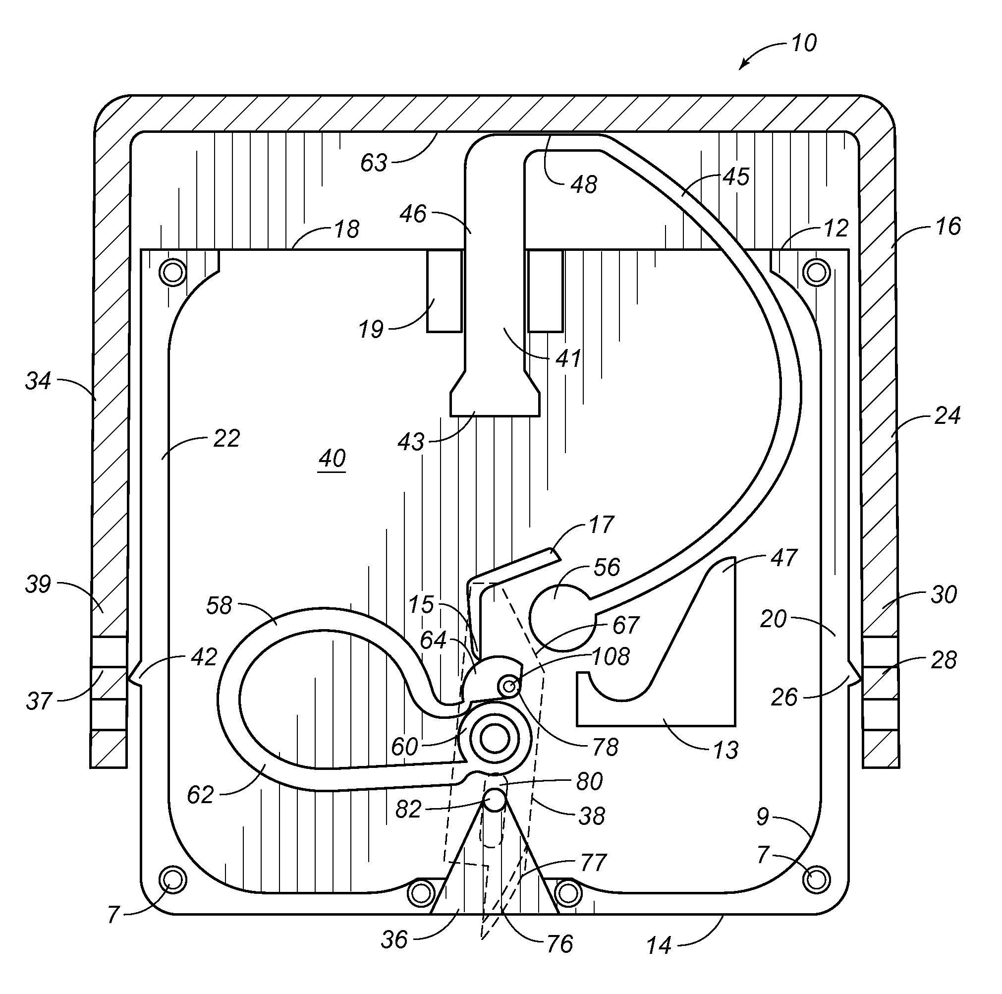
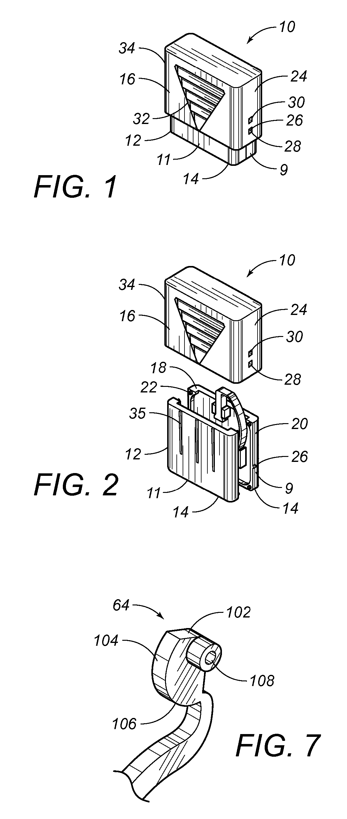
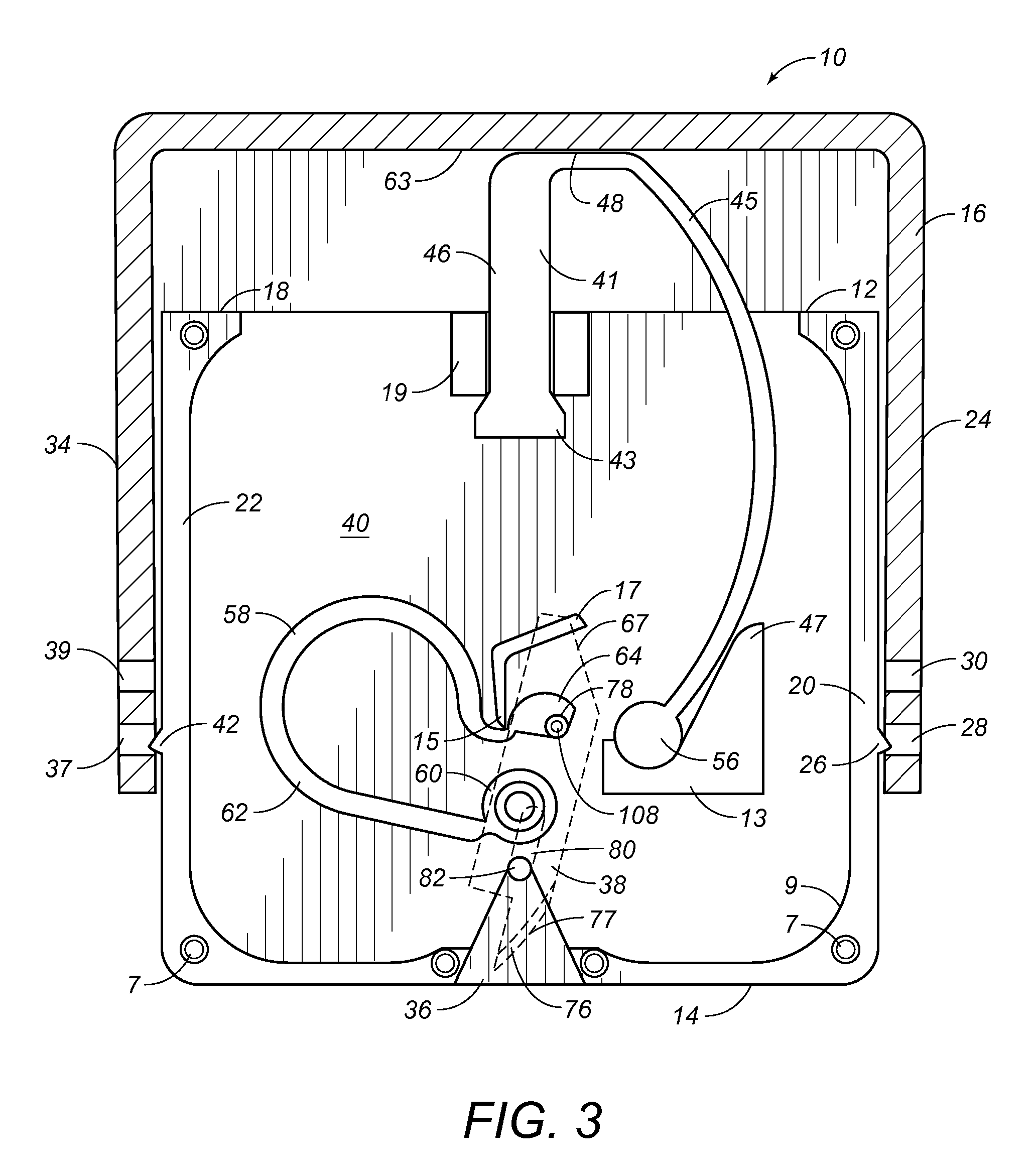
[0043] Referring to FIGS. 1 and 2, there is shown the skin incision device 10 in accordance with the teachings of the preferred embodiment of the present invention. The skin incision device 10 includes a casing 12 having a bottom surface 14 and a cover 16 slidably positioned on the casing 12. The top cover 16 is slidable in a direction transverse to a plane of the bottom surface 14. The casing 12 can have a first panel 9 and a second panel 11.

[0044] The casing 12 has a generally open end 18 opposite the bottom surface 14. The casing 12 has sides 20 and 22 extending upwardly from the bottom surface 14. The cover 16 extends over the open end 18 of the casing 12 and has a wall 24 extending over at least a portion of the side 20 of the casing 12. The side 20 has a barb 26 extending outwardly therefrom. The wall 24 has a first retaining slot 28 and second retaining slot 30 formed above the first retaining slot 28. As can be seen in FIG. 1, the barb 26 engages the first retaining slot 28...


PUM


Abstract

A skin incision device has a casing with a bottom surface and a slot formed therein, a cover positioned on the casing and slidable in a direction toward the bottom surface, a blade positioned in the casing adjacent the slot, an actuator cooperative to a position between the cover and interior of the casing, and a carriage. The actuator engages the blade by its horizontal displacement triggered by slidable movement of the cover toward the bottom surface of the casing. The carriage element guides movement of the blade between a pre-actuated position and a post-actuated position. The blade extends outwardly of the bottom surface with a fixed depth of cut during a horizontal movement of the blade through the slot.

Description

RELATED U.S. APPLICATIONS [0001] The present application is a continuation-in-part application pending priority from U.S. patent application Ser. No. 10 / 792,025, filed on Mar. 3, 2004, and entitled ā€œLoad-Controlled Device for a Patterned Skin Incisionā€, presently pending. U.S. patent application Ser. No. 10 / 792,025 is a continuation-in-part application claiming priority from U.S. patent application Ser. No. 10 / 628,199, filed on Jul. 28, 2003 and entitled ā€œLoad-controlled Auto-actuated Skin Incision Deviceā€, presently pending.STATEMENT REGARDING FEDERALLY SPONSORED RESEARCH OR DEVELOPMENT [0002] Not applicable. REFERENCE TO MICROFICHE APPENDIX [0003] Not applicable. FIELD OF THE INVENTION [0004] The present invention relates to medical devices. More particularly, the present invention relates to devices for incising the skin. In particular, the present invention relates to internal actuators for skin incising devices which apply a controlled load and a constant force during the incis...

Claims


Application Information

Patent Timeline
11 Jan 2007
Publication
US20070010839A1
IPC
A61B17/32; A61B5/15; A61B17/14
CPC
A61B5/1411; A61B5/15142; A61B2019/4873; A61B2019/304; A61B17/32093; A61B5/150022; A61B5/150465; A61B5/150916
Inventors
GALLOWAY, EDWARD L.; PETERSEN, ERIC