Methods and instruments for interbody fusion

a technology of interbody fusion and instruments, which is applied in the direction of prosthesis, surgical forceps, applications, etc., can solve the problems of affecting the inability to maintain the stability of the segment, and the long surgical procedures necessary to implant a rod or plate to stabilize the level during fusion, so as to minimize the trauma to the tissue

Inactive Publication Date: 2007-11-27
WARSAW ORTHOPEDIC INC
View PDF140 Cites 117 Cited by
  • Summary
  • Abstract
  • Description
  • Claims
  • Application Information

AI Technical Summary

Benefits of technology

[0039]In subsequent steps, the distractor is removed and a reamer is advanced through the number of seals of the laparoscope and through the outer sleeve into the disc space to ream the disc space and adjacent vertebrae to create a prepared bore for the fusion implant. After the reamer is removed from the laparoscope, the fusion implant can be advanced through the number of seals and through the outer sleeve into the prepared bore. With the fusion implant in position, the laparoscope can be withdrawn from the patient.
[0040]In one aspect of the invention, a switching sleeve is palced within the outer sleeve of the laparoscope with an end of the switching sleeve projecting beyond the opposite fingers of the outer sleeve, the end of the switching sleeve being tapered to minimize trauma to tissue adjacent the subject disc space as the outer sleeve advanced into the patient with the switching sleeve projecting beyond the opposite extensions of the outer sleeve.
[0041]In a further embodiment, the laparoscopic method is used for bilateral placement of two fusion devices into a subject disc space. In addition to the steps previously described, this embodiment of the surgical technique includes unseating the outer sleeve of the laparoscope from the first opening in the disc annulus by withdrawing the laparoscope until the opposite extensions of the outer sleeve are outside the disc annulus. With the switching sleeve in position within the outer sleeve, the laparoscope is moved to the second opening in the disc space without removing the laparoscope from the patient. The steps for preparing the bore to receive a fusion implant can be repeated. In one specific embodiment, these steps are conducted at the second opening with the distractor remaining within the first opening. After a fusion implant isnced through the number of seals and through the outer sleeve into the second prepared bores the laparoscope can then be returned to the first opening for insertion of another fusion implant. During this step, the fusion implant contained within the second prepared bore maintains distraction of the disc space.

Problems solved by technology

Since the damaged disc material has been removed, something must be positioned within the intra-discal space, otherwise the space may collapse resulting in damage to the nerves extending along the spinal column.
Once fusion occurred the hardware used to maintain the stability of the segment became superfluous.
Moreover, the surgical procedures necessary to implant a rod or plate to stabilize the level during fusion were frequently lengthy and involved.

Method used


Image

  • Methods and instruments for interbody fusion
  • Methods and instruments for interbody fusion
  • Methods and instruments for interbody fusion

Examples


Embodiment Construction

[0045]For the purposes of promoting an understanding of the principles of the invention, reference will now be made to the embodiments illustrated in the drawings and specific language will be used to describe the same. It will nevertheless be understood that no limitation of the scope of the invention is thereby intended, such alterations and further modifications in the illustrated devices, and such further applications of the principles of the invention as illustrated therein being contemplated as would normally occur to one skilled in the art to which the invention relates.

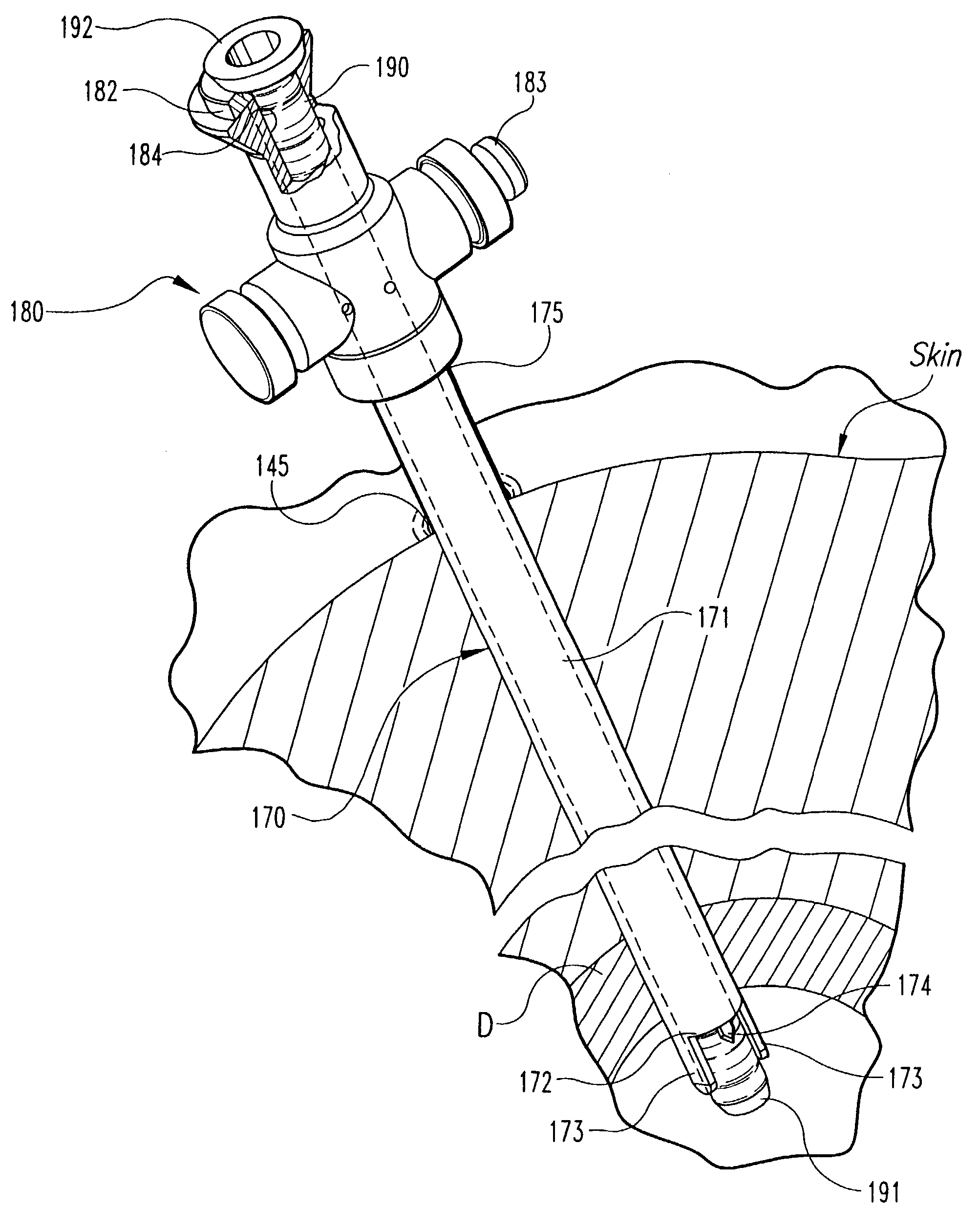
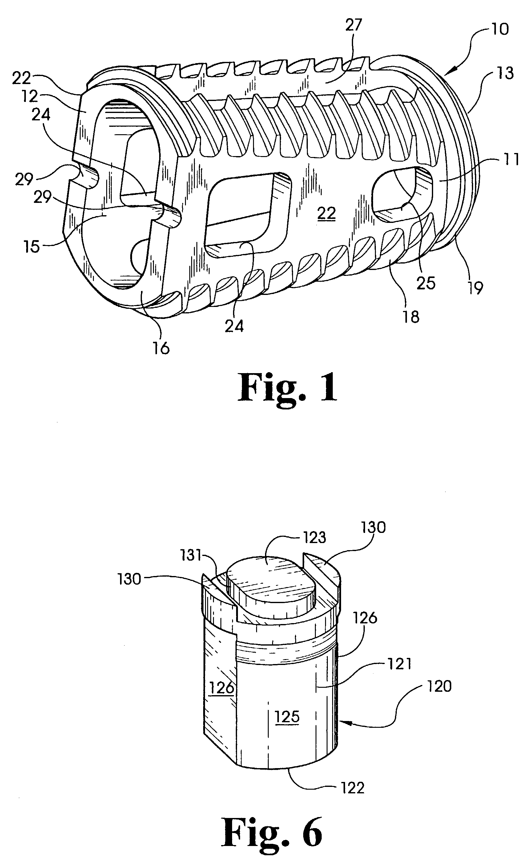
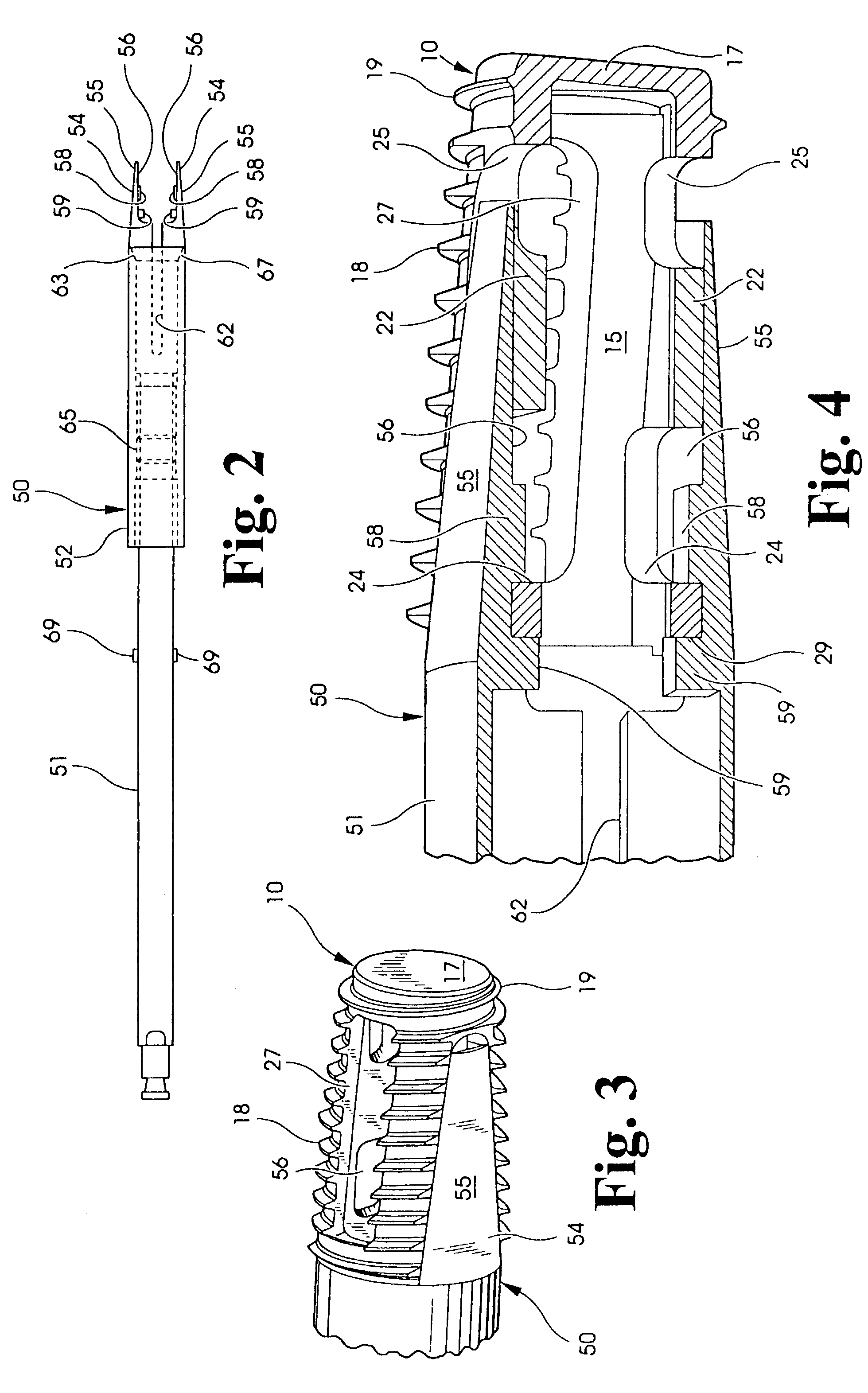
[0046]As described above, one interbody fusion device, as shown in FIG. 1, can be implanted within the intra-discal space. This interbody fusion device 10 can be implanted using the implant driver 50 shown in FIG. 2. The implant driver 50 is comprised of a shaft 51 and sleeve 52 concentrically disposed about the shaft. Tongs 54 are formed at one end of the shaft for gripping the interbody fusion device 10 for ...


PUM

PropertyMeasurementUnit
lengthaaaaaaaaaa
lengthaaaaaaaaaa
depthaaaaaaaaaa

Abstract

A laparoscopic surgical technique is provided for preparing a site for implantation of a fusion device or implant. In accordance with one embodiment of the technique, a laparoscope is provided having an outer sleeve with distraction fingers at one end to distract the disc space. The laparoscope includes a laparoscopic port at its opposite end through which instruments and implants are inserted. The laparoscope provides a sealed working channel to the disc space, through which the disc space is distracted, the vertebral endplates and surrounding disc is reamed, and the fusion device inserted. The laparoscope is alternately engaged within bilateral locations in the disc space for insertion of a pair of fusion implants. A switching sleeve extends through the laparoscope to protect the tissue at the surgical site as the laparoscope is moved between the bilateral fusion locations.

Description

BACKGROUND OF THE INVENTION[0001]This application is a continuation of U.S. patent application Ser. No. 09 / 746,300, filed Dec. 21, 2000 now U.S. Pat. No. 6,595,995, which is a continuation of U.S. patent application Ser. No. 09 / 265,179, filed Mar. 9, 1999, now U.S. Pat. No. 6,245,072, issued Jun. 12, 2001, which is a continuation of U.S. patent application Ser. No. 09 / 176,972, filed Oct. 22, 1998, now abandoned, which is a continuation of U.S. patent application Ser. No. 08 / 604,874, filed Feb. 22, 1996, now abandoned, which is a continuation-in-part of U.S. Pat. No. 08 / 411,017, filed Mar. 27, 1995, now U.S. Pat. No. 5,782,919, issued Jul. 21, 1998.[0002]The present invention relates to methods and instruments for performing an interbody fusion of a disc space between two adjacent vertebrae. Specifically, the invention concerns laparoscopic techniques and instruments to prepare a fusion site and to insert fusion devices and implants.[0003]The number of spinal surgeries to correct the...

Claims


Application Information

Patent Timeline
Patent Type & Authority Patents(United States)
IPC IPC(8): A61B17/32A61B1/313A61B17/00A61B17/02A61B17/16A61B17/17A61B17/28A61B17/34A61B17/70A61B17/86A61B17/88A61B19/00A61F2/00A61F2/28A61F2/30A61F2/44A61F2/46
CPCA61B1/3132A61B1/3135A61B17/025A61B17/1671A61B17/1757A61B17/282A61F2/4455A61F2/446A61F2/4601A61F2/4611A61F2/4637A61L27/227A61L31/047A61B17/7059A61B17/86A61B17/8883A61B17/8891A61B2017/00238A61B2017/00261A61B2017/0256A61B2017/3488A61B2019/5404A61B2019/5437A61F2/30744A61F2/30767A61F2/442A61F2002/2835A61F2002/2839A61F2002/30123A61F2002/30136A61F2002/30143A61F2002/30153A61F2002/30158A61F2002/30179A61F2002/3021A61F2002/30217A61F2002/30329A61F2002/30433A61F2002/30504A61F2002/30507A61F2002/30774A61F2002/30777A61F2002/30785A61F2002/30787A61F2002/30789A61F2002/3082A61F2002/3085A61F2002/30858A61F2002/30863A61F2002/30871A61F2002/30874A61F2002/4475A61F2002/448A61F2002/4627A61F2002/4635A61F2002/464A61F2002/4641A61F2220/0025A61F2220/0041A61F2230/0004A61F2230/0006A61F2230/0017A61F2230/0019A61F2230/0026A61F2230/0058A61F2230/0067A61F2310/00017A61F2310/00023A61F2310/00095A61F2310/00131A61F2310/00161A61F2310/00179A61F2310/00796A61F2002/305A61F2002/30593A61F2002/30873A61B2090/3904A61B2090/3937
Inventor ZDEBLICK, THOMASBOYD, LAWRENCE M.RAY, III, EDDIE
Owner WARSAW ORTHOPEDIC INC
Why Eureka
Try Eureka