Parachute release apparatus

a technology of parachute and release mechanism, which is applied in the direction of emergency apparatus, parachutes, transportation and packaging, etc., can solve the problems of pyrotechnic charges posing a substantial hazard to the personnel preparing the cargo delivery system and the aircraft, and the parachute system to fail,

Inactive Publication Date: 2007-03-22
FOX JR ROY L
View PDF15 Cites 5 Cited by
  • Summary
  • Abstract
  • Description
  • Claims
  • Application Information

AI Technical Summary

Benefits of technology

[0023] In the second means, each suspension strap is secured by a loop to a release arm, as in the first means. However, the suspension strap traverses down and through a clevis, yoke, or the like on the cargo platform, forming a bight around the clevis, and then traverses back up again and is fixed to the release body. When the release arms are released from the inner latch plates, the first end of the suspension straps are released, and the first half of the suspension straps slide through the shackles on the cargo platform as the cargo platform descends away from the release mechanism. The suspension straps remain

Problems solved by technology

At times, people in isolated areas, such as jungles, deserts, mountains, polar regions, or combat zones, are in need of essential supplies, including food and medical supplies, but are not within access to an airport at which a supply plane could land.
Use of a series of parachute deployments is often necessary because the force and impulse on the suspension lines and straps of a main parachute (i.e., one large enough to slow the cargo platform to an acceptable landing velocity) deploying at the terminal, free-fall velocity of the cargo platform would be excessive, causing the parachute system to fail.
The release mechanism must release all attached suspension slings simultaneously, otherwise the suspended cargo platform will pitch or roll after release, jeopardizing successful deployment of the next parachute.
These larger pyrotechnic charges pose a substantial hazard to th

Method used


Image

  • Parachute release apparatus
  • Parachute release apparatus
  • Parachute release apparatus

Examples


Embodiment Construction

[0036] The following discussion describes in detail one or more embodiments of the invention. The discussion should not be construed, however, as limiting the invention to those particular embodiments, and practitioners skilled in the art will recognize numerous other embodiments as well. The complete scope of the invention is defined in the claims appended hereto.

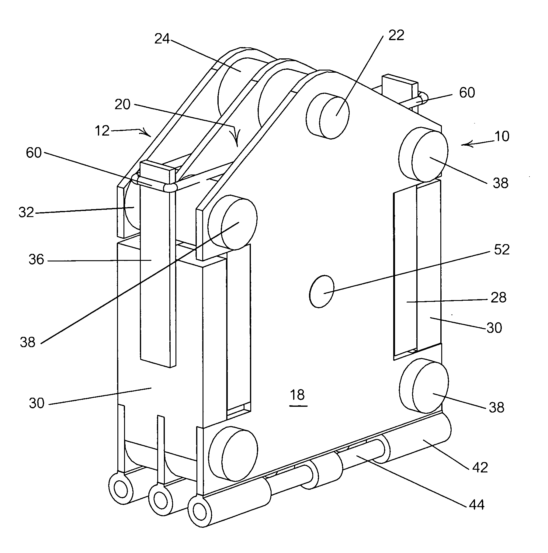
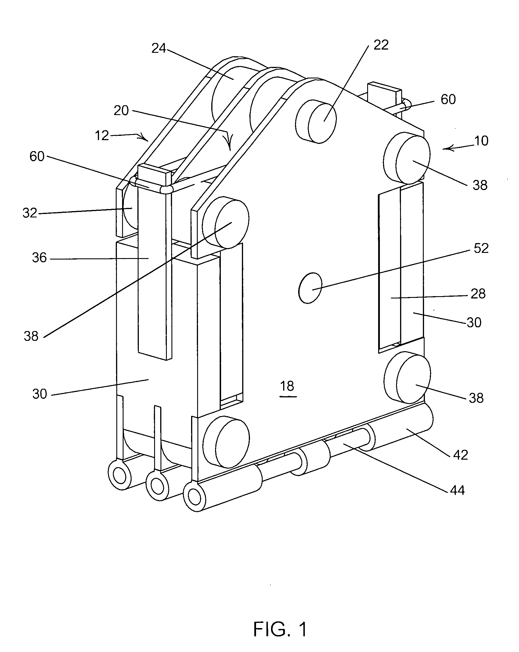
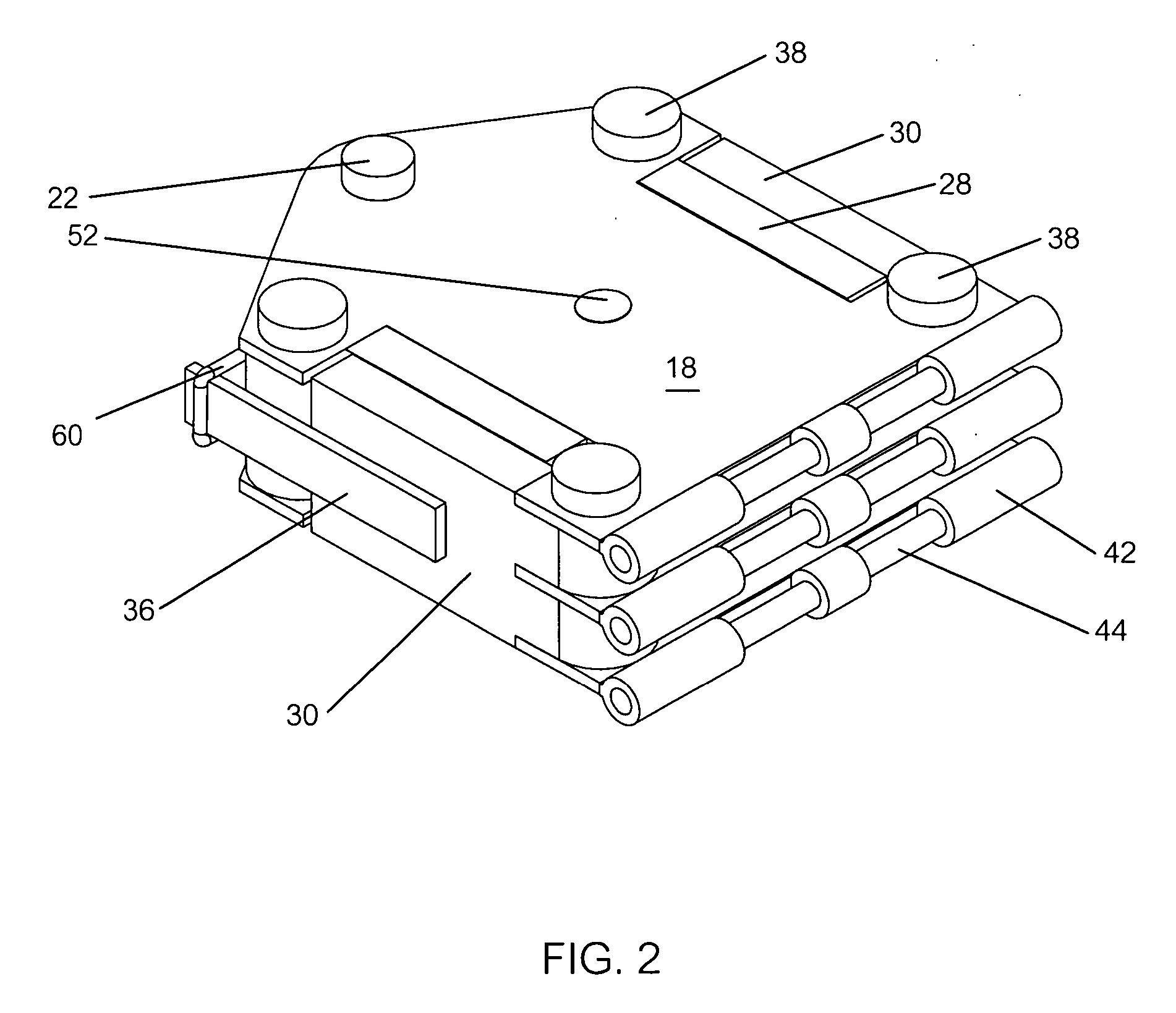
[0037] Within the appended figures, a parachute release apparatus is generally referenced as 10.

[0038] As illustrated in FIGS. 1 and 2, a parachute release apparatus 10 is comprised of a pendant body 12, which typically is comprised of a plurality of flat pendant body plates 18 disposed with their faces in parallel, thus defining one or more cavity spaces 20 between the pendant body plates 18. The pendant body plates 18 are held in place by a plurality of pins installed transversely between the pendant body plates 18. An upper clevis pin 22 is installed near the top of the pendant body 12. The upper clevis pin 22 may be ...


PUM


Abstract

A parachute release apparatus for controllably and timely releasing a drogue parachute from a descending, aerially delivered cargo platform. The parachute release apparatus is comprised of a pendant body with multiple parallel plates. Cavities are defined between each two parallel plates of the pendant body. Latch mechanisms are disposed on either side of the pendant body. Each latch mechanism is comprised of an articulating outer and inner plate. Within each cavity is a pair of release arms which articulate with the pendant body. Either release arm engages with the inner latch plate of each latch mechanism. The latch mechanisms are maintained in a latched configuration by a cut loop attached to extension arms on either outer latch plate, and are released by a pyrotechnic cutter disposed on the cut loop. A plurality of suspension straps are coupled with the apparatus, which are enshrouded in a bifurcated sleeve.

Description

BACKGROUND OF THE INVENTION [0001] 1. Field of the Invention [0002] The present invention relates to parachute release mechanisms for releasing a deployed parachute from a suspended load in a controlled manner. [0003] 2. Description of the Prior Art [0004] Aerial delivery is a means frequently used for transporting cargo quickly to areas of limited or hostile access, without the availability of any nearby airports. At times, people in isolated areas, such as jungles, deserts, mountains, polar regions, or combat zones, are in need of essential supplies, including food and medical supplies, but are not within access to an airport at which a supply plane could land. In these instances, aerial delivery of cargo from in-flight aircraft is the sole option. These aerial delivery systems involve the use of parachute systems to slow the descent and gently land the cargo platforms on the ground. [0005] Similar parachute systems are further utilized for recovery of aeronautical and astronautic...

Claims


Application Information

Patent Timeline
IPC IPC(8): B64D17/00
CPCB64D17/62
Inventor FOX, ROY L. JR.
Owner FOX JR ROY L
Why Eureka
Try Eureka