

Monolithic digital audio bus switch with output control
a digital audio bus and output control technology, applied in the field of digital audio bus switches, can solve the problems of imposing extra cost on the design, consuming board space, and increasing the cost of devices, and achieve the effect of simple logic control
- Summary
- Abstract
- Description
- Claims
- Application Information
AI Technical Summary
Benefits of technology
Problems solved by technology
Method used
Image

Examples
Embodiment Construction
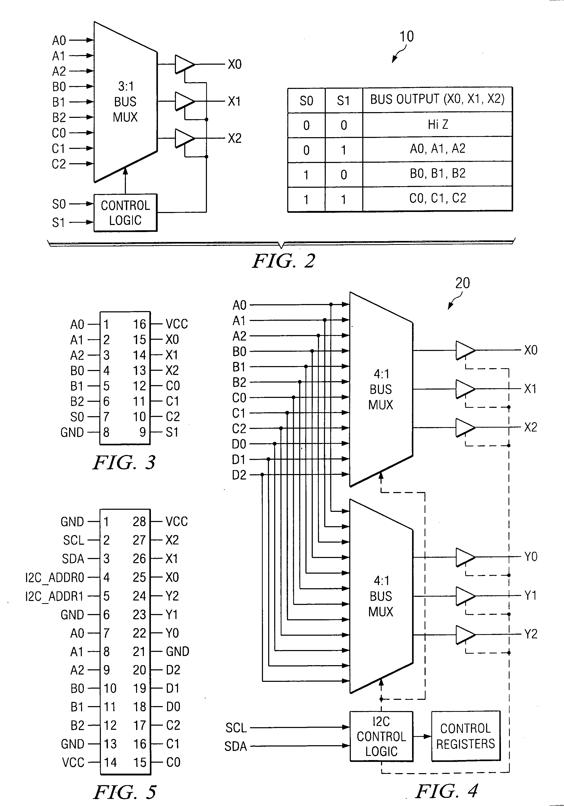
[0018] Two preferred embodiments of the invention. The first preferred embodiment is shown as 3:1 3-bit bus switch with simple logic control. The second preferred embodiment is slightly more complex, shown as 4:2 bus switch with a I2C interface that can output any of four inputs on either of the two outputs. The invention is extremely useful in present & future audio applications.
[0019]FIG. 2 shows a device block diagram for the first preferred embodiment of the invention seen to comprise 3:1 bus switch 10, and FIG. 3 shows a pinout of switch 10. The switch 10 is shown as a 16-pin device in TSSOP or SOIC package, and operates from a 3.3 V supply. Switch 10 accepts three 3-bit bus inputs (3.3 V and 5 V levels), and drives one 3-bit bus output. The switch 10 is controlled via two control logic control signals (S0, S1) provided by control logic. The control logic for these muxes is preferably digital, but the actual muxes (switches) can be implemented using digital logic or analog swi...
PUM
 Abstract
Description
Claims
Application Information