Joint apparatus of car windshield wiper arm

Inactive Publication Date: 2007-03-29
HUANG SHIH HSIEN
View PDF0 Cites 4 Cited by
  • Summary
  • Abstract
  • Description
  • Claims
  • Application Information

AI Technical Summary

Benefits of technology

[0009] The main object of the present invention is to provide a joint apparatus of car windshield wiper arm, which comprises a upper cover body and a chassis; Exploiting the round groove cut of the upper cover body and the fixing pivot on the chassis being intimately engaged each other to serve as a pivot, as well as the guiding gap and the horizontal elastic embed hook of the upper cover body and the insetting hole on the chassis being inset each other, hence, the rigging assembly and dismantling of said wiper arm with curbing head and said wiper can be rapidly and time-saving accomplished.
[0010] The other object of the present invention is to provide a joint apparatus of car windshield wiper arm: During the operation procedure of replacing worn wiper blade by new one, not only the effort-wasting in alert to the alignment of fixing spindle with spindle hole can be saved, but also said wiper needless to overturn, hence it will not hit the replacing operator or not unexpectedly re-bounce back to resume its original horizon status under inadvertently touch said curbing head of said wiper arm by hand due to any carelessness, thus serious drawback of hurt the windshield G in accompanied consequence of said curbing head directly strike the surface of said windshield G can be avoided.

Problems solved by technology

However, during practical operation of replacing worn windshield wiper by new one, there are some drawbacks of aforementioned joint apparatus as below:

Method used


Image

  • Joint apparatus of car windshield wiper arm
  • Joint apparatus of car windshield wiper arm
  • Joint apparatus of car windshield wiper arm

Examples


Embodiment Construction

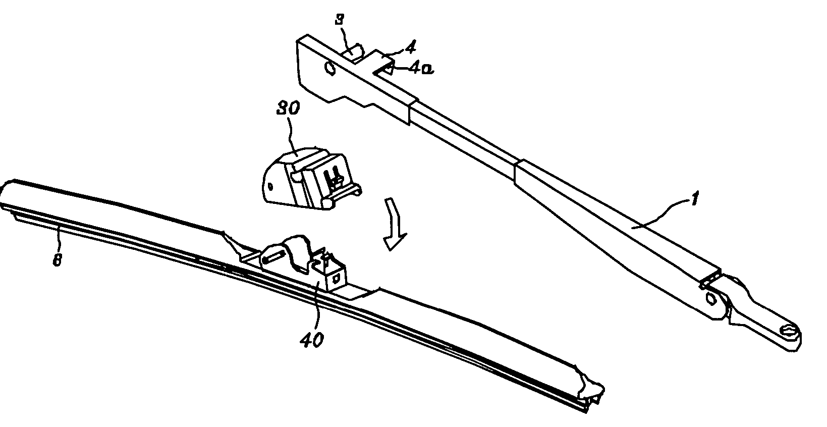
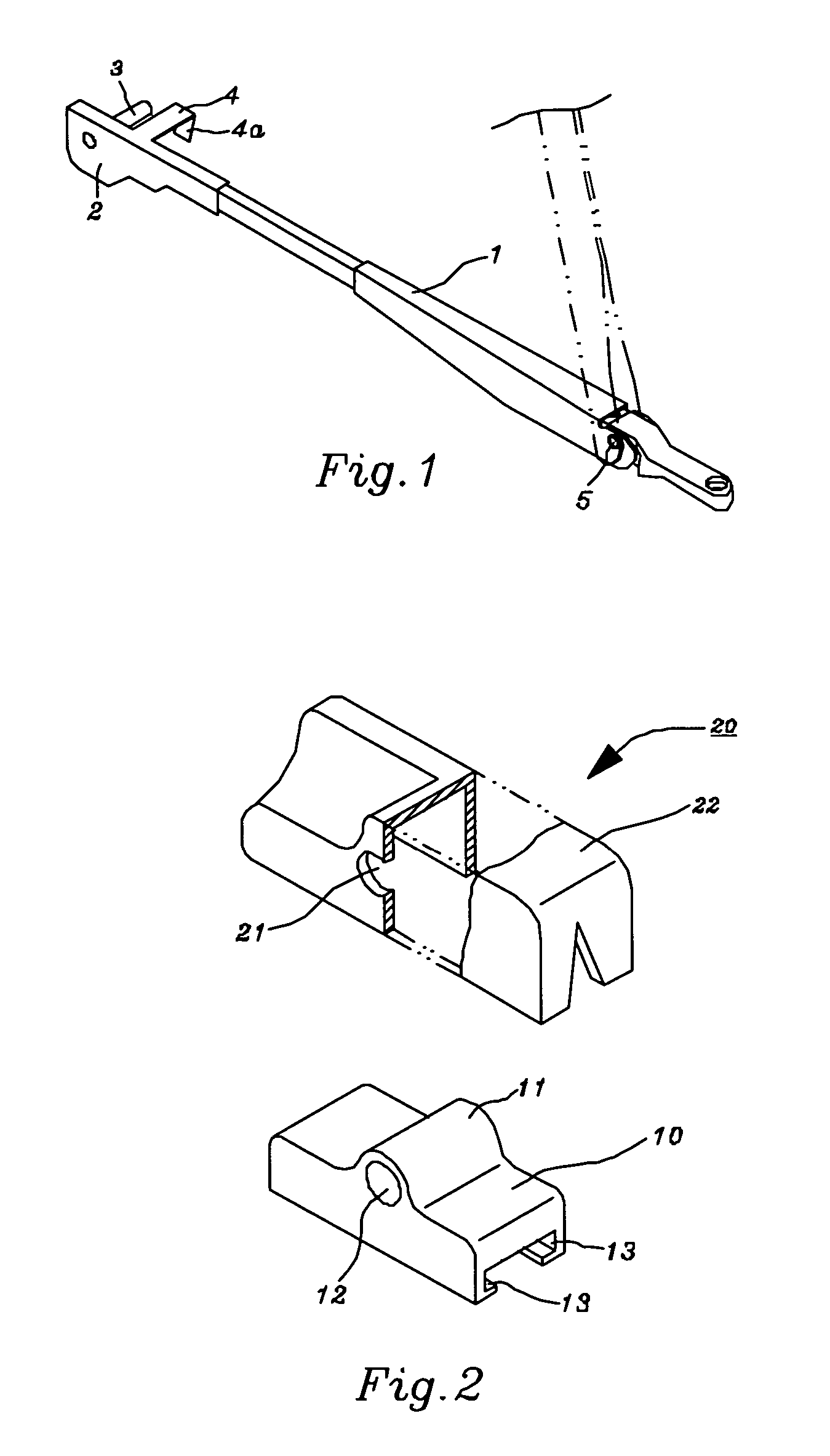
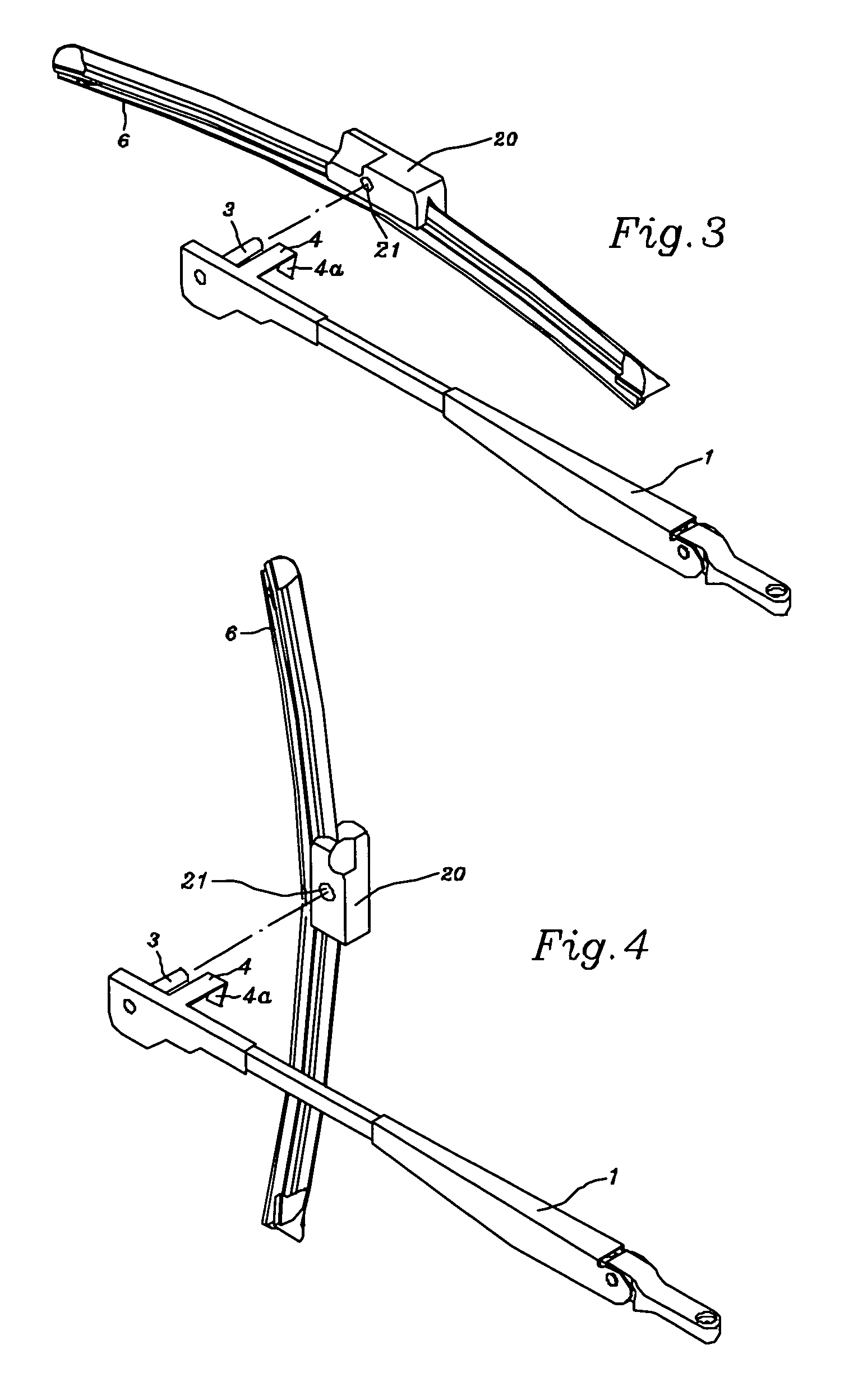
[0033] Referring to FIG. 10 through FIG. 14, the present invention “joint apparatus of car windshield wiper arm” comprises:

[0034] an upper cover body 30, which comprises a front top surface 31, a rear top surface 32, a front side 33, a left side 34, a right side 35 and a rear side 36, wherein a guiding gap 37, which is concaved between said front top surface 31 and said rear top surface 32, has a adjacent round groove receptacle 38 indented at its bottom portion towards said front top surface 31; said front side 33 and said front top surface 31 joint internally together to make a solid core 39 inside (as shown in the FIG. 12); some distance exists between both sides upright of the bottom side 391 of said core 39 and said left side 34 as well as said right side 35 for creating each left groove cut 392 and right groove cut 393 respectively (as shown in the FIG. 11); a round groove cut 394 with V-shaped cross-section is concaved near said front side 33; a back-end face 395 is upwards ...


PUM


Abstract

The present invention is to provide a joint apparatus of car windshield wiper arm, which comprises a upper cover body and a chassis; wherein said upper cover body having a round groove cut with V-shaped cross-section is concaved near the bottom side of the front side; a guiding gap is concaved between said front top surface and said rear top surface; a horizontal round groove receptacle and a vertical hollow socket are respectively created at said guiding gap; a horizontal elastic embed hook is built at the center between said rear side; and said chassis having a pair of parallel and symmetrical left plate and right plate are upwards built at the front section, and a horizontal fixing pivot is bridged near the front end; an upright curbing plate is upwards formed in the middle section of the bottom plate; a insetting hole is perforated at the center of the rear plate. By means of the round groove cut of the upper cover body and the fixing pivot on the chassis being intimately engaged each other to serve as a pivot, as well as the horizontal elastic embed hook of the upper cover body and the insetting hole on the chassis being inset each other respectively, thus, the insetting securely in rigging assembly or the dismantling in replacement of wiper arm with curbing head to or from between the joint apparatus of the wiper can be quickly accomplished.

Description

FIELD OF THE PRESENT INVENTION [0001] The present invention relates to a joint apparatus of car windshield wiper arm, more particularly being contrived for the curbing-type wiper arm with fixing spindle and press curbing strip. Hence, it not only satisfies with the demand of fixing and curbing press but also provides the more quick and simpler operation effect. Thus, the operation of replacing worn wiper by new one becomes fast, rapid and easy and smooth. BACKGROUND OF THE PRESENT INVENTION [0002] Presently, the types in head of windshield wiper arm are many in variety. Different type design of wiper arm head must be coordinated with its exclusive joint apparatus to enable securely joint each other. Such as USA issued patents U.S. Pat. No. 6,516,491, U.S. Pat. No. 6,687,948, U.S. Pat. No. 6,782,581, U.S. Pat. No. 6,836,927, U.S. Pat. No. 6,836,926 and U.S. Pat. No. 6,910,244 as well as USA published patents S2004 / 0025280, US2005 / 0039292, US2004 / 0098821 and US2004 / 0117938, all disclo...

Claims


Application Information

Patent Timeline
IPC IPC(8): B60S1/40
CPCB60S1/3848B60S1/3867B60S1/4077B60S1/407B60S1/40
Inventor HUANG, SHIH-HSIEN
Owner HUANG SHIH HSIEN
Why Eureka
Try Eureka