Pressure detection device

a detection device and pressure technology, applied in the direction of instruments, pedestrian/occupant safety arrangements, force/torque/work measurement apparatus, etc., can solve the problems of impaired transference of pressure of the exterior to the detection surface, hampered liquid flow downward,

Inactive Publication Date: 2007-04-19
DENSO CORP
View PDF5 Cites 4 Cited by
  • Summary
  • Abstract
  • Description
  • Claims
  • Application Information

AI Technical Summary

Benefits of technology

[0010] In view of the above-described disadvantages, it is an object of the present invention to provide a pressure detection device which has a satisfactory reliability even in a wet environment.
[0012] Thus, air can be introduced into the pressure introduction passage through the third opening portion which is positioned at the upper side of the second opening portion, to restrict a pressure decrease in the upper portion of the pressure introduction passage when the pressure introduction passage is blocked by liquid and the like having entered therein. Therefore, the liquid and the like can be readily discharged from the pressure introduction passage through the second opening portion. Accordingly, the pressure can be substantially detected via the pressure detection unit.

Problems solved by technology

However, when liquid such as rain intrudes into the pressure introduction passage through the lower opening portion so that the pressure introduction passage is blocked, the upper space of the pressure introduction passage will become a closed space.
Because the gravity of the liquid is counterbalanced due to a pressure decrease of the closed upper space, the liquid is hampered from flowing downward (i.e., from being discharged from pressure introduction passage).
Particularly, in the case where the liquid is solidified due to a temperature decrease or the like, the transference of the pressure of the exterior to the detection surface is impaired.

Method used


Image

  • Pressure detection device
  • Pressure detection device
  • Pressure detection device

Examples


first embodiment

(First Embodiment)

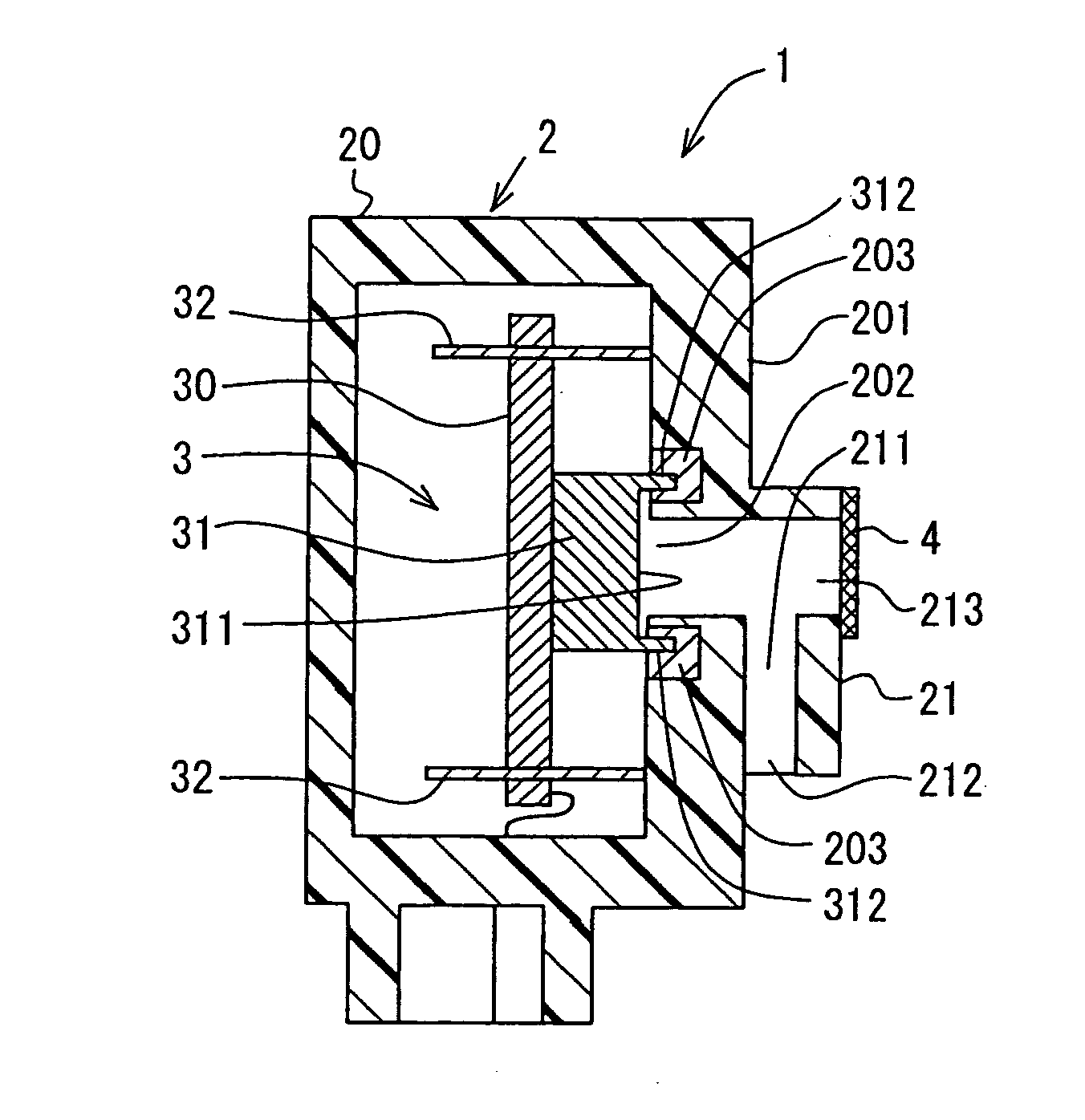
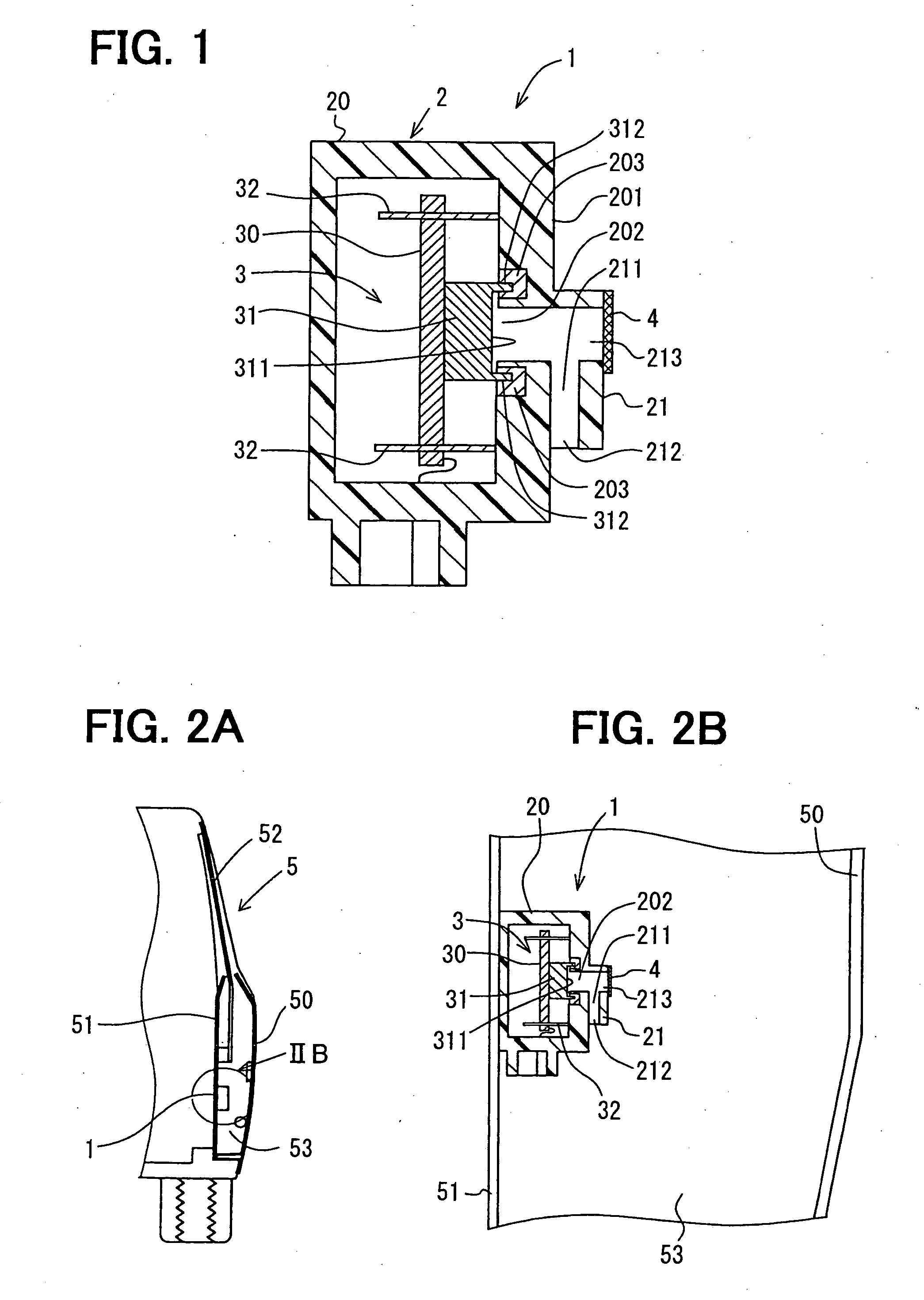
[0018] A pressure detection device 1 according to a first embodiment will be described with reference to FIGS. 1-2B. The pressure detection device 1 can be suitably used in a passenger protecting system of a vehicle for the sake of a collision detection of the vehicle, for example.

[0019] As shown in FIG. 1, the pressure detection device 1 is provided with a case unit 2, a circuit assembly 3 and a filter 4. The circuit assembly 3 has a circuit board 30 and a pressure detection unit 31 which is mounted to the circuit board 30. The pressure detection unit 31 has a detection surface 311 for detecting a pressure applied thereto.

[0020] The case unit 2 can be made of a resin or the like. The case unit 2 has a housing member 20 defining therein an accommodation space in which the circuit assembly 3 is accommodated, and a passage member 21 defining therein a pressure introduction passage 211. The passage member 21 has a tubelike shape, for example.

[0021] The housing memb...

second embodiment

(Second Embodiment)

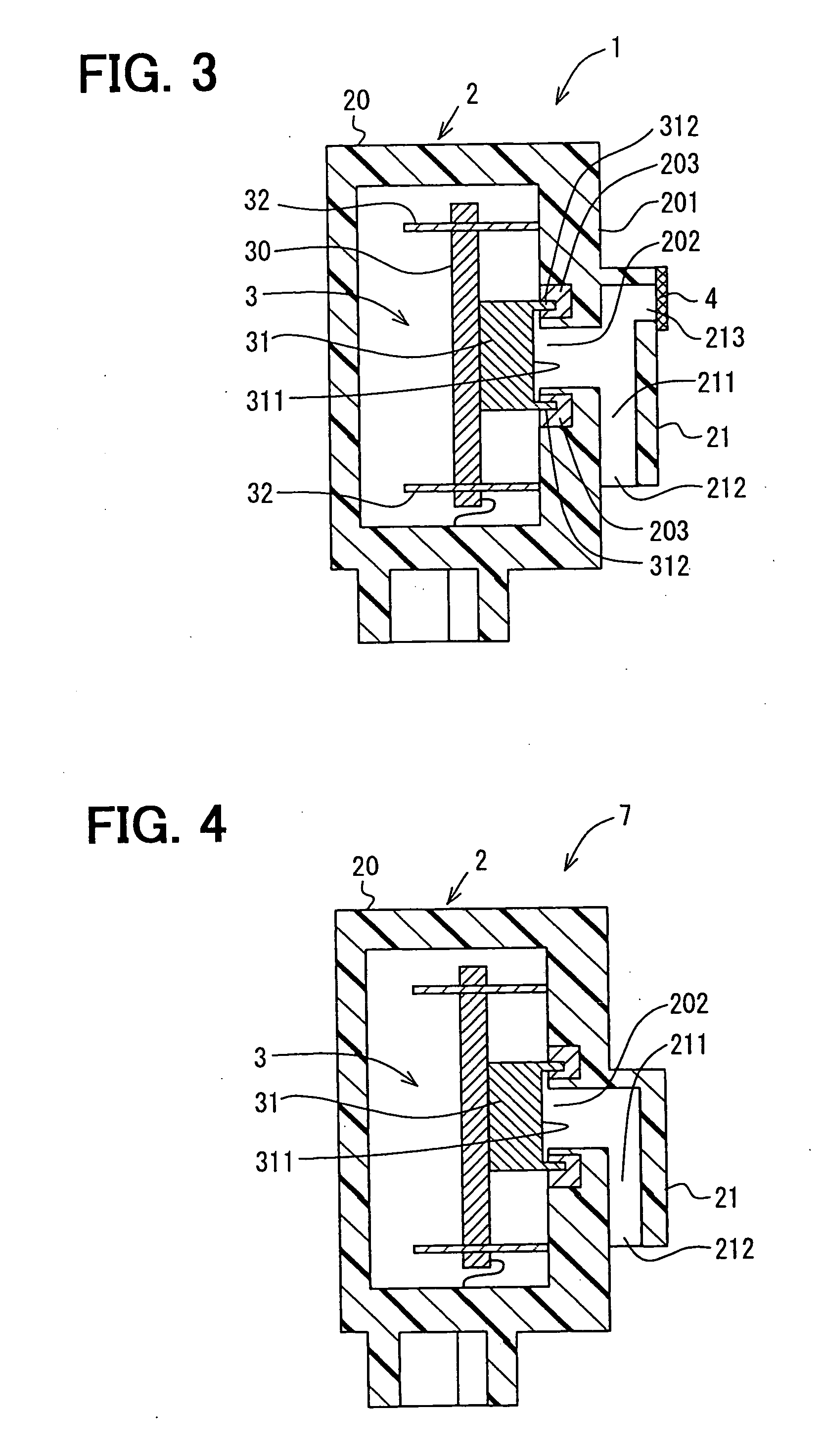
[0055] A second embodiment will be described with reference to FIG. 3. In this case, the passage member 21 of the pressure detection device 1 further extends toward the opposite side to the lower opening portion 212, so that the upper opening portion 213 and the lower opening portion 212 are respectively arranged at the two opposite sides (in extension direction of passage member 21) of the housing opening portion 202.

[0056] In this case, the pressure detection device 1 is attached to the vehicle or the like in such a manner that the upper opening portion 213 is positioned at the upper side of the housing opening portion 202 (detection surface 311). That is, the detection surface 311 is disposed to detect the pressure, with the upper opening portion 213 being positioned at the upper side of the housing opening portion 202 (detection surface 311) and the lower opening portion 212. The upper opening portion 213 is covered by the breathable filter 4.

[0057] Accordin...


PUM

PropertyMeasurementUnit
pressureaaaaaaaaaa
perimeteraaaaaaaaaa
perimetersaaaaaaaaaa

Abstract

A pressure detection device includes a case unit which has therein an accommodation space and a pressure introduction passage, and a pressure detection unit having a detection surface for detecting a pressure applied thereto. Two ends of the pressure introduction passage respectively have a first opening portion which is opened toward the accommodation space, and a second opening portion which is opened toward an exterior of the case unit. The pressure detection unit is accommodated in the accommodation space. The pressure introduction passage further has a third opening portion which is opened toward the exterior. The pressure detection unit is disposed to detect the pressure, with the first opening portion and the third opening portion being positioned at an upper side of the second opening portion.

Description

CROSS REFERENCE TO RELATED APPLICATION [0001] This application is based on a Japanese Patent Application No. 2005-304346 filed on Oct. 19, 2005, the disclosure of which is incorporated herein by reference. FIELD OF THE INVENTION [0002] The present invention relates to a pressure detection device. BACKGROUND OF THE INVENTION [0003] Generally, a vehicle is provided with a passenger protecting system for protecting passengers in a collision of the vehicle. The passenger protecting system has, for example, an airbag device for deploying an airbag to protect the head portion or the like of the passenger, and / or a pre-tensioner device for taking up a slack of a seat belt of the vehicle. [0004] The airbag device and the pre-tensioner device are controlled by a control unit such as an ECU. The ECU performs a determination of the vehicle collision based on signals from sensors mounted to the vehicle, and actuates the airbag device and the pre-tensioner device when the vehicle collision is de...

Claims


Application Information

Patent Timeline
Patent Type & Authority Applications(United States)
IPC IPC(8): B60R21/26B60R21/16B60R21/00G01L5/00G01L19/00
CPCB60R21/0136B60R2021/01006
Inventor WANAMI, SHINGOMURAI, TOSHIYUKI
Owner DENSO CORP
Why Eureka
Try Eureka