Semiconductor-component device assembled on a heat sink, assembly method, and lighting device for a motor vehicle including such a device

a technology of semiconductor components and heat sinks, which is applied in the direction of fixed installation, lighting and heating apparatus, and association of printed circuit non-printed electric components, etc., can solve the problems of hindering the visibility of the operator, affecting the operation of the device, and the assembly method is further exacerbated. , to achieve the effect of convenient and fast assembly of the different elements, less cost, and satisfactory reliability

Active Publication Date: 2016-03-31
VALEO VISION SA
View PDF8 Cites 6 Cited by
  • Summary
  • Abstract
  • Description
  • Claims
  • Application Information

AI Technical Summary

Benefits of technology

[0014]The invention is intended to overcome the drawbacks in the prior art by providing an assembly method for a lighting device that is less costly while ensuring satisfactory reliability and easy—and therefore rapid—assembly of the different elements of the lighting device.

Problems solved by technology

However, although the method known from the prior art saves the operator assembling the semiconductor component from having to perform an additional electrical wire management step when positioning the heat sink on the related supporting element, this method presents a greater problem: it is costly in that, firstly, the choice of materials used to manufacture the first connector portion is determined by the installation requirements of the printed circuit board, i.e. high temperatures (within a range of approximately 200-300° C.
Secondly, the assembly method as known from the prior art is particularly lengthy since, once the heat sink has been positioned on the related lighting supporting element, it is then necessary to connect the second connector portion, linked to the group of electrical wires, to the first connector portion on the printed circuit board, which is done in a confined and therefore relatively inaccessible space formed between the supporting element and the heat sink, which may be difficult.
This difficulty is further exacerbated by the presence of floating electrical wires which hinder the visibility of the operator when connecting the two connector portions, and which are also likely to come between the mechanical elements to be assembled, during this step of the method or during a subsequent step.
The duration of the method known from the prior art undoubtedly results in a loss of profitability since it involves implementing such a method on a large scale (i.e. on a series of lamps on a production line).

Method used


Image

  • Semiconductor-component device assembled on a heat sink, assembly method, and lighting device for a motor vehicle including such a device
  • Semiconductor-component device assembled on a heat sink, assembly method, and lighting device for a motor vehicle including such a device
  • Semiconductor-component device assembled on a heat sink, assembly method, and lighting device for a motor vehicle including such a device

Examples


Embodiment Construction

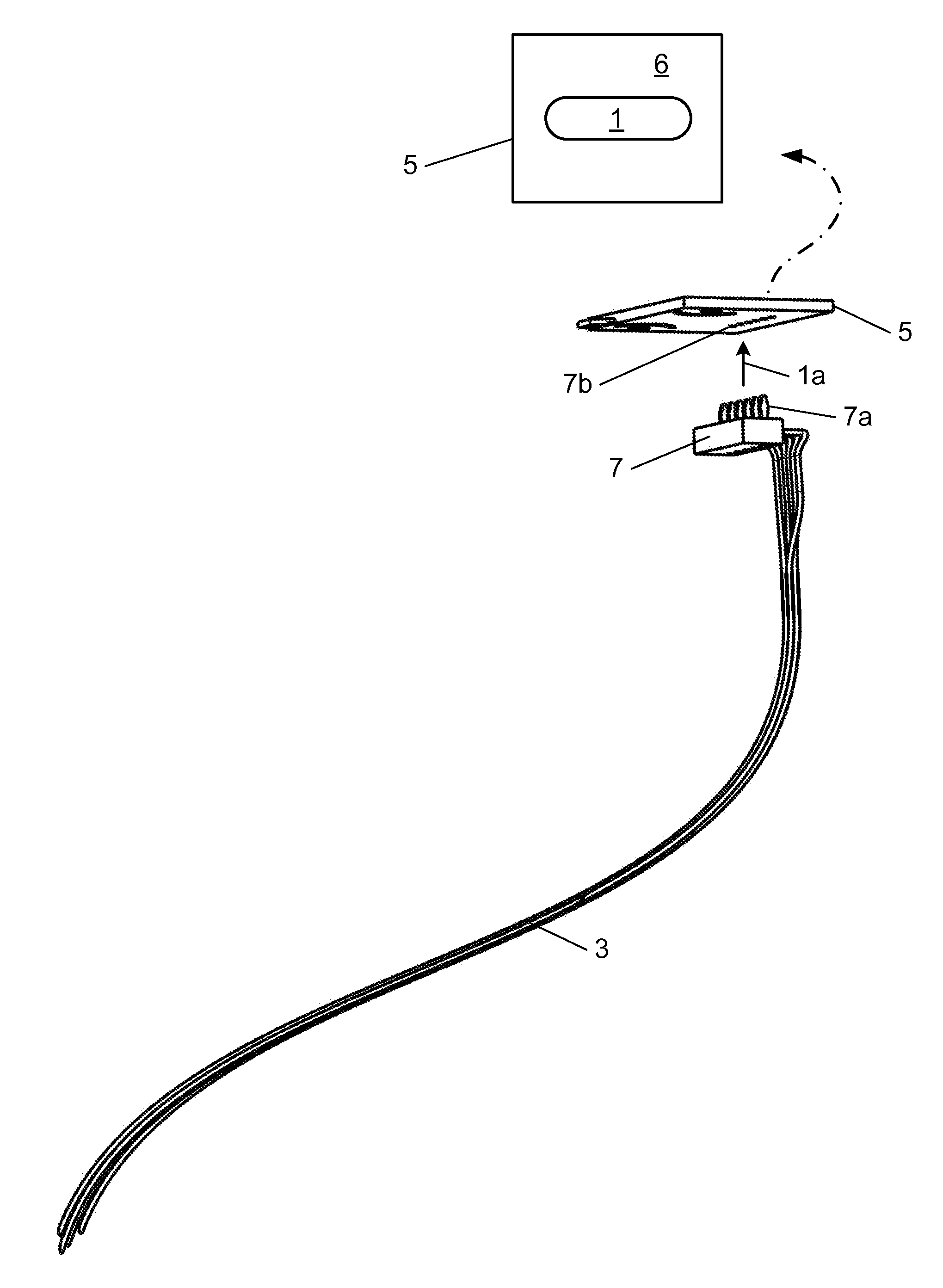
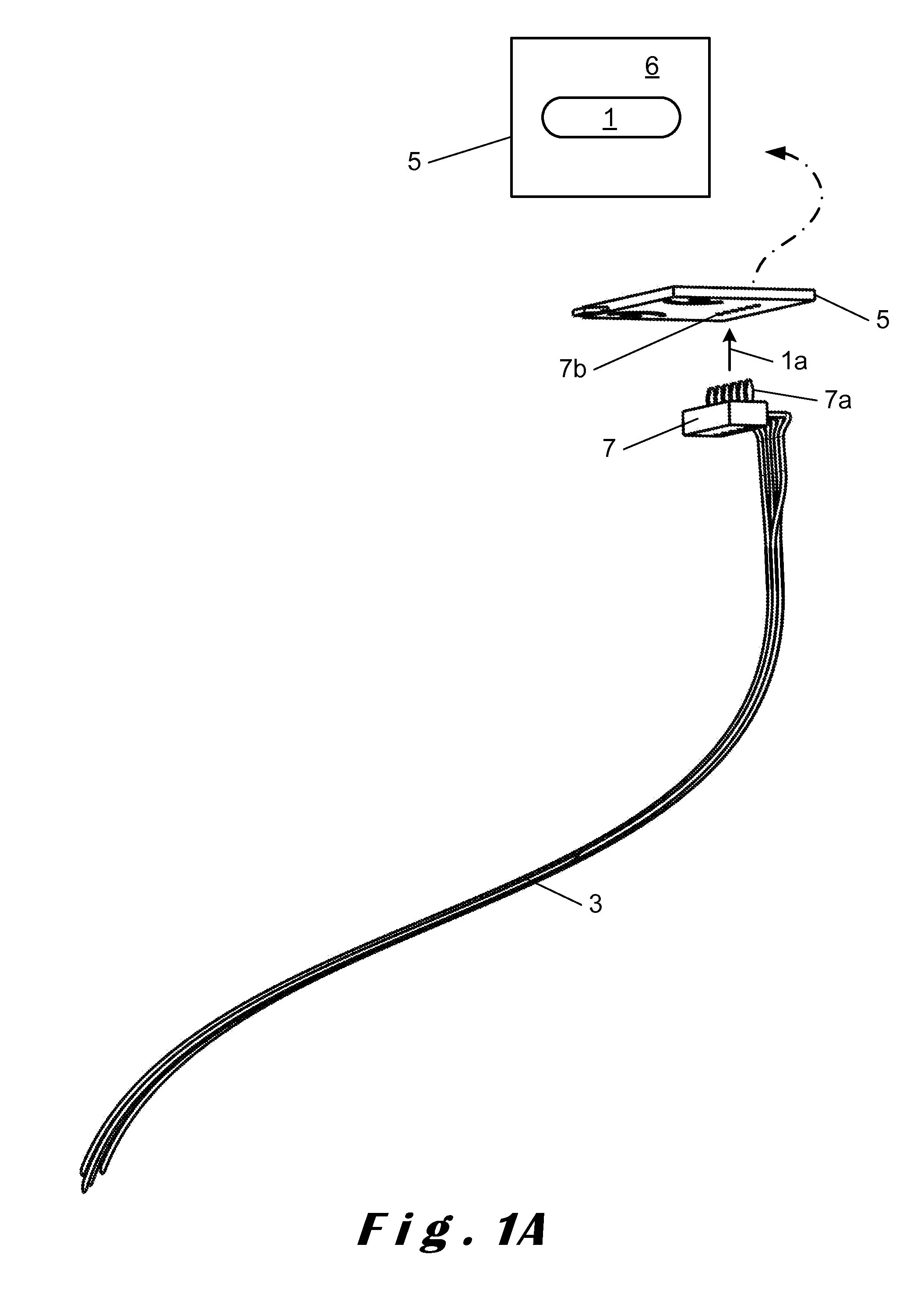
[0049]The steps for assembling an electronic semiconductor component 1 on a heat sink according to the first embodiment of the method according to the present invention are illustrated in FIGS. 1A to 1E.

[0050]The assembly method mentioned above includes a first step 1a in which a group 3 of electrical wires is attached to a rear face of an electrical connection element 5, which is a printed circuit board (PCB), the front face 6 of which carries the semiconductor component, for example a light emitting diode (LED) 1 (FIG. 1A). A variant of the embodiment in which the LED 1 is assembled on the PCB 5 involves the LED 1 being assembled directly on the heat sink, then connected to the PCB 5, for example by wire solder.

[0051]During this first step 1a, the group 3 of electrical wires is attached to the PCB 5 by means of a one-piece connector 7 (or single connector) linked electrically and mechanically to the group 3 such that the PCB 5 is connected physically and electrically to each of th...


PUM


Abstract

A device including at least one semiconductor component connected to an electrical connection element, the electrical connection element is attached to a heat sink and connected to a group of electrical wires, the group being linked mechanically and electrically to the electrical connection element by a single connector, the group being linked to the heat sink by holding means.

Description

CROSS-REFERENCE TO RELATED APPLICATIONS[0001]This application claims priority to the French application 1459309 filed on Sep. 30, 2014, which application is incorporated herein by reference and made a part hereof.BACKGROUND OF THE INVENTION[0002]1. Field of the Invention[0003]The invention relates to a semiconductor-component device assembled on a heat sink, the semiconductor component being connected to an electrical connection element.[0004]The invention also relates to a method for assembling the aforementioned device, and to a lighting device for a motor vehicle incorporating such a device.[0005]The present invention is specifically intended for use in the assembly of a light source in a motor vehicle lamp.[0006]2. Description of the Related Art[0007]In the domain of motor vehicle lighting, when using light-emitting diodes (LEDs, which are semiconductor components) as a light source, it is known to assemble these LEDs on an electrical connection element, for example a printed ci...

Claims


Application Information

Patent Timeline
Patent Type & Authority Applications(United States)
IPC IPC(8): F21S8/10B60Q1/00F21W107/10H05K1/11H05K1/18H05K3/30H05K3/32H05K7/20
CPCF21S48/328H05K7/20409H05K1/181B60Q1/0088H05K3/303H05K3/32F21S48/215H05K1/11F21V17/10F21S43/14F21S43/19F21S45/48
Inventor MORNET, ERICDUCLOUX, BRUNOYACOUBI, NADIALETOUMELIN, REMIPUENTE, JEAN-CLAUDEMATTE, FRANCKJACQUEMIN, DIDIER
Owner VALEO VISION SA
Why Eureka
Try Eureka