

Multi-functional law enforcement tool
a multi-functional, law enforcement technology, applied in the direction of gymnastic exercise, repellant gas/chemical self-defence devices, lighting and heating apparatus, etc., can solve the problems of escalating the situation, difficult to find the space to place separate objects around her belt, etc., to achieve greater communication ability, quick at hand, and convenient to carry
- Summary
- Abstract
- Description
- Claims
- Application Information
AI Technical Summary
Benefits of technology
Problems solved by technology
Method used
Image

Examples
first embodiment
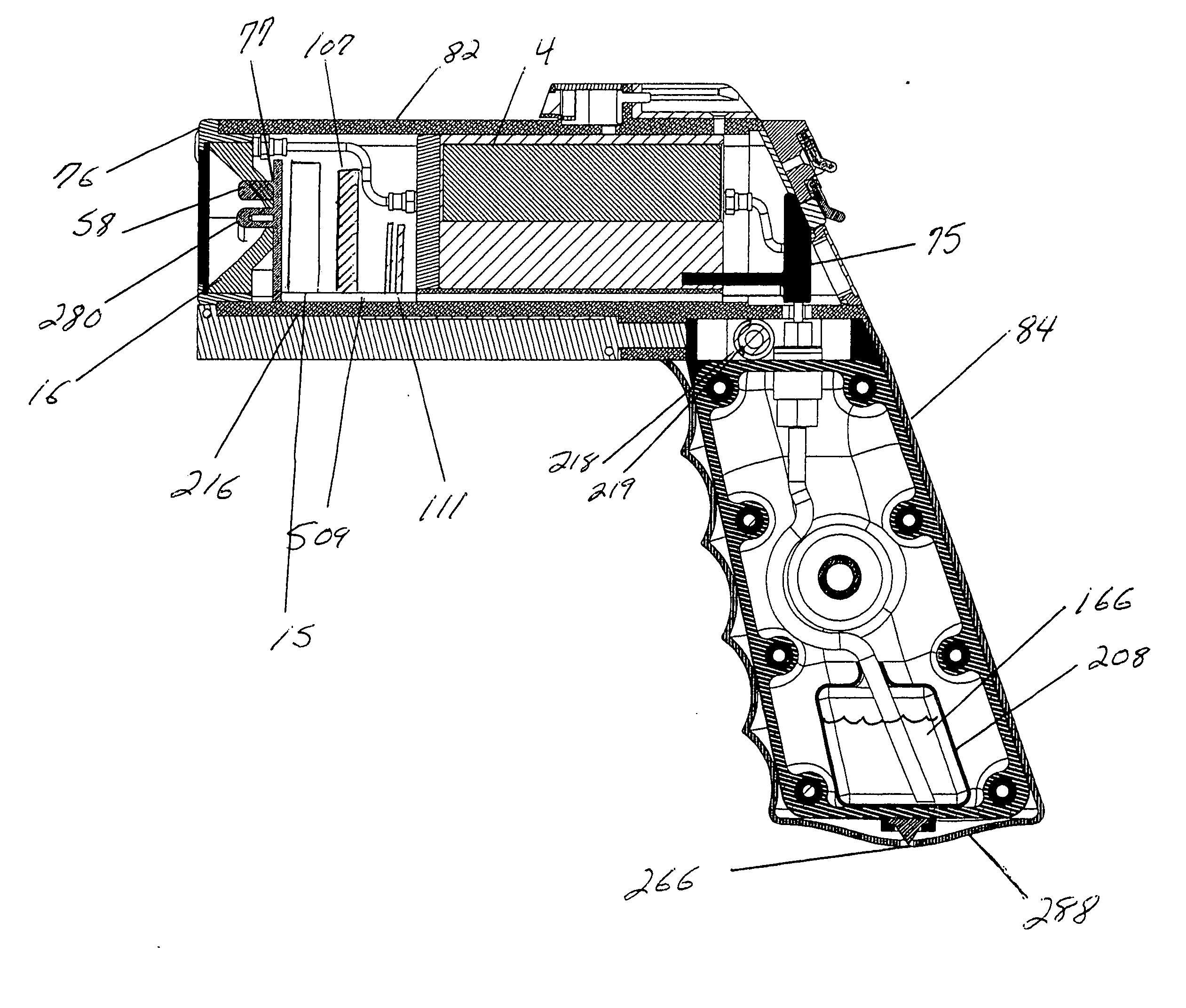
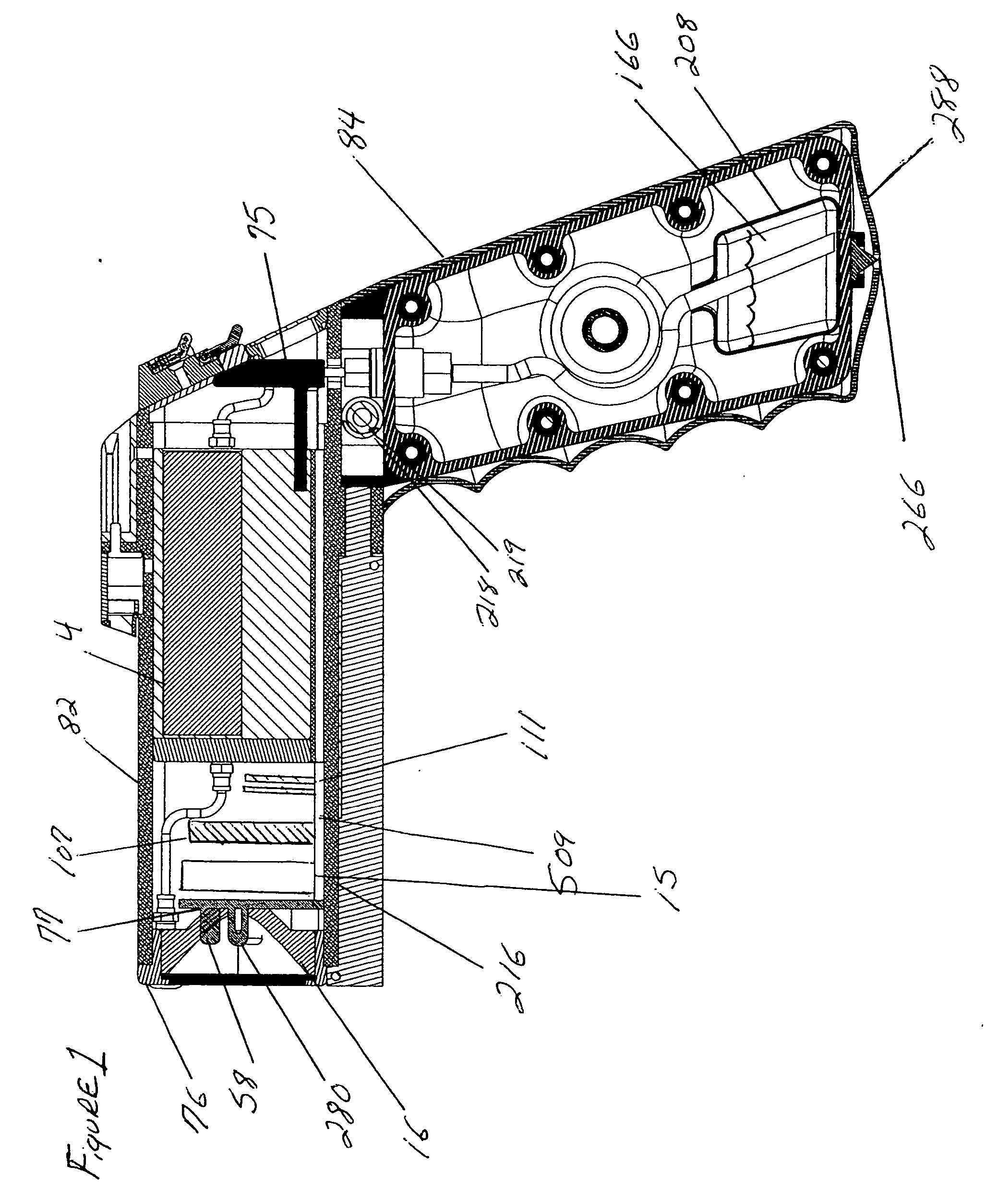
[0036]FIG. 1 depicts the invented multifunctional law enforcement tool, which comprises a handle unit. According to these Figures, FIG. 1 comprises an Exterior Shell 82 and a Handle Canister 84. The interchangeably connectable orthogonal Handle Canister 84 preferably extends integrally from Exterior Shell 82, wherein interchangeably connected Handle Canister 84 houses Deterrent Spray Bladder 208 of FIG. 1, Deterrent Spray Liquid 166 of FIG. 1, Spray Stems 210 and 211 of FIG. 5, and Air Intake Valve 212 of FIG. 6. Handle Canister 84 is connected and held in place by Retractable Pins 213 and 214 of FIG. 5 and Compressible Spring 215 of FIG. 5. The Retractable Pins 213 and 214 connect Handle Canister 84 to Cartridge Housing 216 of FIG. 1 by expanding into Cartridge Housing Holes 218 and 219 of FIG. 1, locking it into place. The interchangeably connectable orthogonal Handle of FIG. 5 maintains a Rubber Grip cover 288 which not only acts as a grip for the user, but includes a compressibl...
second embodiment
[0045] In the Multifunctional Law Enforcement Tool, FIG. 13 depicts a Defense Shield 885, a Defense Shield Housing 837, a Stationary Handle 313, and the Multifunctional Tool of FIG. 1 coupled together to create an offensive and defensive shield. The user simply slides the Multifunctional Law Enforcement Tool of FIG. 1 forward into Defense Shield Housing 837 of FIG. 13 until Shield Lock 809 of FIG. 14 securely locks the Multifunctional Tool, creating a handle. The user holds this handle and Stationary Handle 313 of FIG. 13, and is now prepared to use all the offensive tools of the Multifunctional Tool, such as firing projectiles or deterrent spray in an offensive manner, as well as using the Defense Shield 885 of FIG. 13 to defend against thrown kicks, punches or debris in a defensive manner. The user still maintains the ability to use the flashlight, LED light, laser sight and audio / video camera, but loses the ability to use the gun mount and stun gun features.
[0046] In a third embo...
fifth embodiment
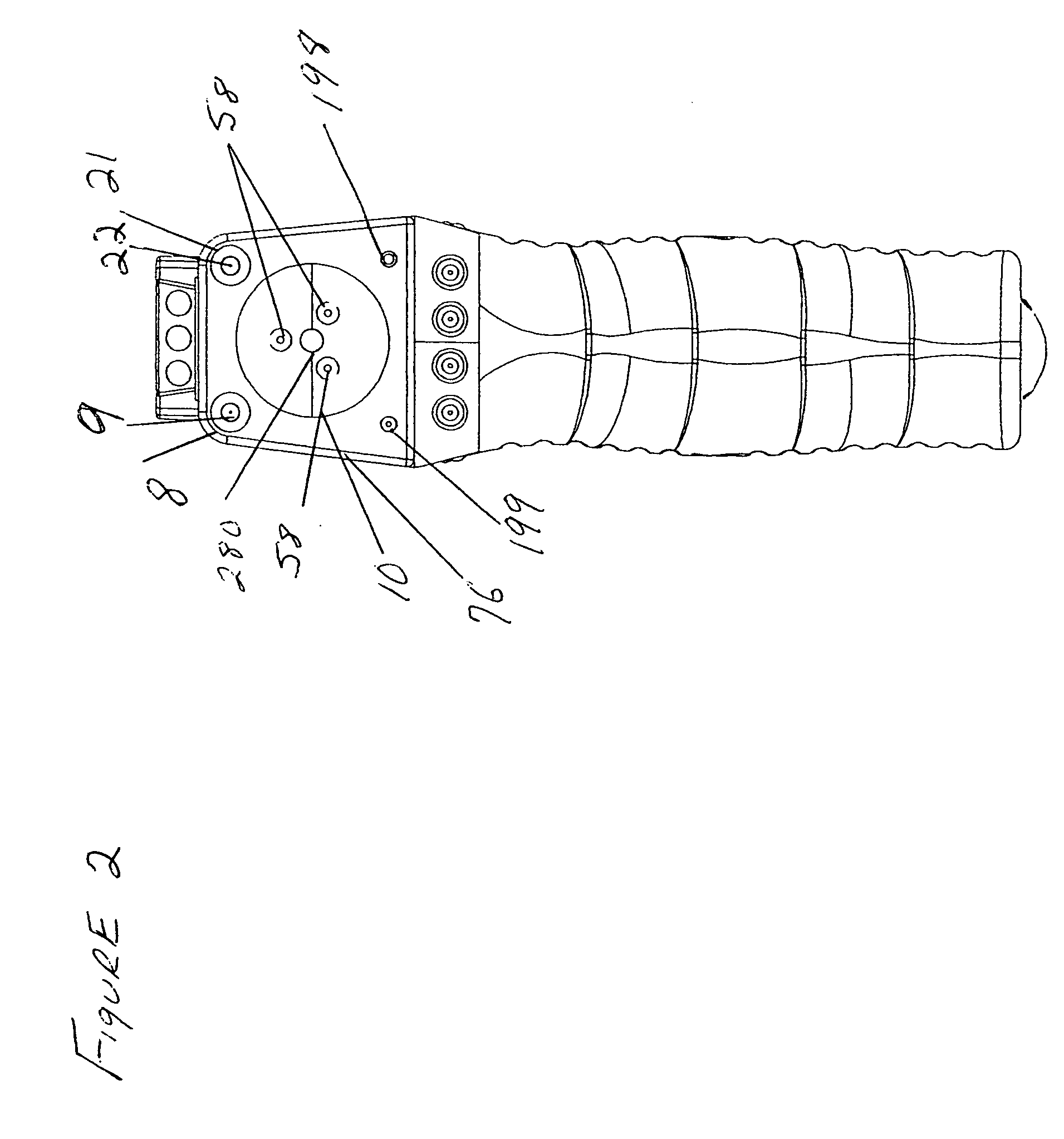
[0048] In a fifth embodiment, by simply changing the Handle Canister 84 of FIG. 1 to Handle Canister 85 of FIG. 16, the user gains a function called “Deterrent Spray Stun” or D.S.S. D.S.S. is a byproduct of the Stun Gun and Deterrent Spray features. The high voltage are between Stun Gun Probes / Battery Recharge Contact 8 and 21 of FIG. 2 is intercepted by the two conductive high pressure deterrent spray streams as they exit deterrent spray exit ports 22 and 9 of FIG. 2. This combination propels and exposed high voltage arc along the conductive streams to the target which completes the circuit and causes a neuromuscular disruption. This feature is able to take place in Handle Canister 85 of FIG. 16 because the Dual Bladders 955 and 956 of FIG. 16 house the deterrent spray separately from one another. The high voltage arc will first travel backwards into the can but will not be able to complete the circuit because Bladders 955 and 956 of FIG. 16 are separate and insulated from one anot...
PUM
 Abstract
Description
Claims
Application Information