Intrusion detection and location system for use on multimode fiber optic cable

a multi-mode fiber optic cable and intrusion detection technology, applied in the direction of instruments, optical elements, optical waveguide light guides, etc., can solve the problems of affecting the idss, burdening processing power, and adding to the complexity of the network

Active Publication Date: 2007-06-14
NETWORK INTEGRITY SYST
View PDF3 Cites 39 Cited by
  • Summary
  • Abstract
  • Description
  • Claims
  • Application Information

AI Technical Summary

Benefits of technology

[0008] It is one object of the present invention to provide an arrangement for detecting movement of an optical fiber which overcomes the limitations with power loss detection methods and can detect intrusion activity before any optical power loss occurs.

Problems solved by technology

However, this adds to the complexity of the network and burdens processing power.
Current IDSs are hampered by Base-Rate Fallacy limitation, which is the inability to suppress false alarms.
Additionally, software-based IDSs do not provide protection against passive optical fiber tapping, which can go undetected by the network hardware.
This causes a small spatial distortion in the core / cladding guiding properties and a fraction of the light escapes the fiber.
This results in a loss of received optical power of only 0.04 or 0.004 dB and is impossible to detect reliably by power measurement methods.

Method used


Image

  • Intrusion detection and location system for use on multimode fiber optic cable
  • Intrusion detection and location system for use on multimode fiber optic cable
  • Intrusion detection and location system for use on multimode fiber optic cable

Examples


Embodiment Construction

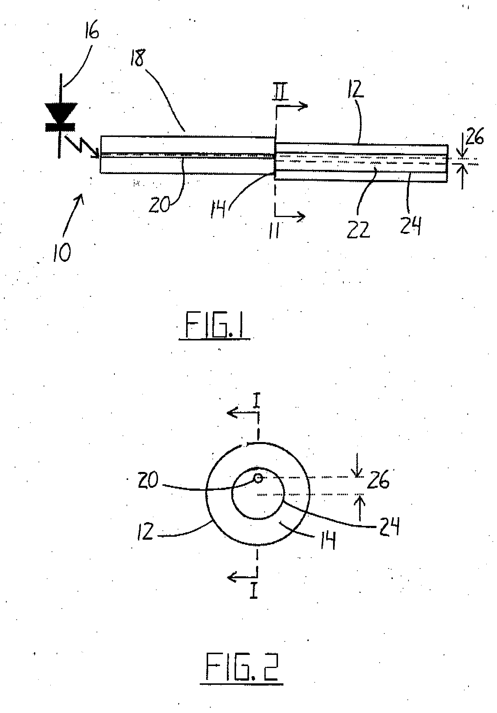
[0046] Referring to the accompanying drawings, and particularly to FIGS. 1 and 2, a transmitter 10 is illustrated for setting up a narrow spectral width, under-filled, non-uniform mode field power distribution in a multimode optical fiber 12. With this type of mode field, the power distribution in the higher order modes changes with physical disturbance of the fiber, despite the absence of any power loss caused by the disturbance.

[0047] The non-uniform high order mode field may be set up in the multimode fiber 12 by illuminating the proximal (near) or transmit end 14 of the fiber with a point source of light that is offset from the center of the optical fiber core. This can be accomplished by a using a laser, optical lenses and positioning mechanics. In the illustrated embodiment, however, this is accomplished more simply by launching a laser 16 into a short length of single mode fiber 18 spliced to the multimode fiber with the center of its core 20 offset from the center of the co...


PUM


Abstract

A telecommunications multimode optical fiber is secured against intrusion by detecting manipulation of the optical fiber prior to an intrusion event. Pulses are injected using a launch arrangement which generates a narrow spectral width, under-filled, non-uniform mode field power distribution in the multimode optical fiber and Fresnel reflections and Rayleigh backscattering from the pulse are detected at the transmit end to monitor the modal power distribution in the fiber which changes on manipulation of the fiber. The Rayleigh backscattering time sliced data can be stored in a register until an intrusion event is detected. The detection is carried out by a modal power distribution detection system which includes an optical coupler to tap off a portion of the light which contains the higher order signal modes.

Description

[0001] This application claims the benefit of the priority date under 35USSC119 from Provisional Application 60 / 704,913 filed 3 Aug. 2005. [0002] The present invention relates to the detection and location of physical intrusion into a multimode fiber optic cable. [0003] This application is related to application Ser. No. 11 / 137,777 filed 26 May 2005 which is a continuation-in-part application of PCT Application PCT / US2004 / 021268 filed 2 Jul. 2004, the disclosure of which is incorporated herein by reference. [0004] This application is related to application Ser. No. 11 / 152,680 filed Jun. 15, 2005 for AN INTRUSION DETECTION SYSTEM FOR USE ON SINGLE MODE OPTICAL FIBER, the disclosure of which is incorporated herein by reference.BACKGROUND OF THE INVENTION [0005] Multimode fiber optic backbone cables are being deployed to connect sections of high-speed networks together, and for long distance communications. To secure these high-speed networks, software based Intrusion Detection Systems...

Claims


Application Information

Patent Timeline
Patent Type & Authority Applications(United States)
IPC IPC(8): G02B6/00G02B6/26
CPCG02B6/14G02B6/24G02B6/421H04B10/071
Inventor MURPHY, CARY R.BRIDGES, MARK H.VOKEY, DAVID E.
Owner NETWORK INTEGRITY SYST
Why Eureka
Try Eureka