Transmission Circuit and Related Method

a technology of transmission circuit and related method, which is applied in the direction of logic circuit coupling/interface arrangement, pulse technique, baseband system details, etc., can solve the problems of prior art, affecting the quality of signal transmission and signal distortion of the receiving circuit, and increasing the power dissipation and layout area used

Active Publication Date: 2007-07-05
VIA TECH INC
View PDF14 Cites 15 Cited by
  • Summary
  • Abstract
  • Description
  • Claims
  • Application Information

AI Technical Summary

Problems solved by technology

However, as known by those skilled in the art, the natural characteristics of the connection (the connection length and the equivalent output impendence and load of the connection) and the signal itself (the levels of frequency and clock) affect the quality of the signal transmission and the signal distortion of the receiving circuit.
However, there are disadvantages of the prior art.
First, the technique of the prior art uses two transmitters to sy...

Method used


Image

  • Transmission Circuit and Related Method
  • Transmission Circuit and Related Method
  • Transmission Circuit and Related Method

Examples


Embodiment Construction

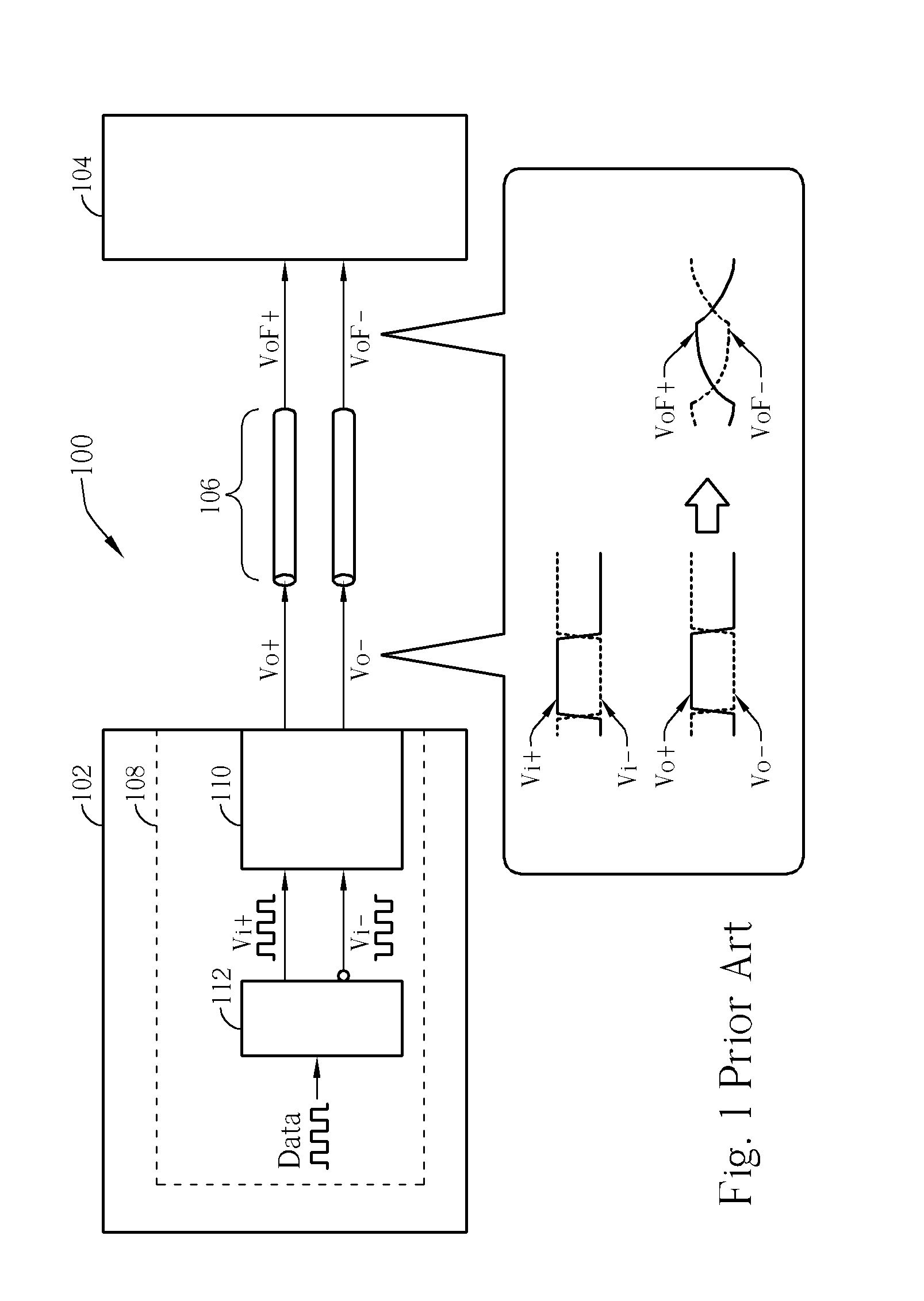
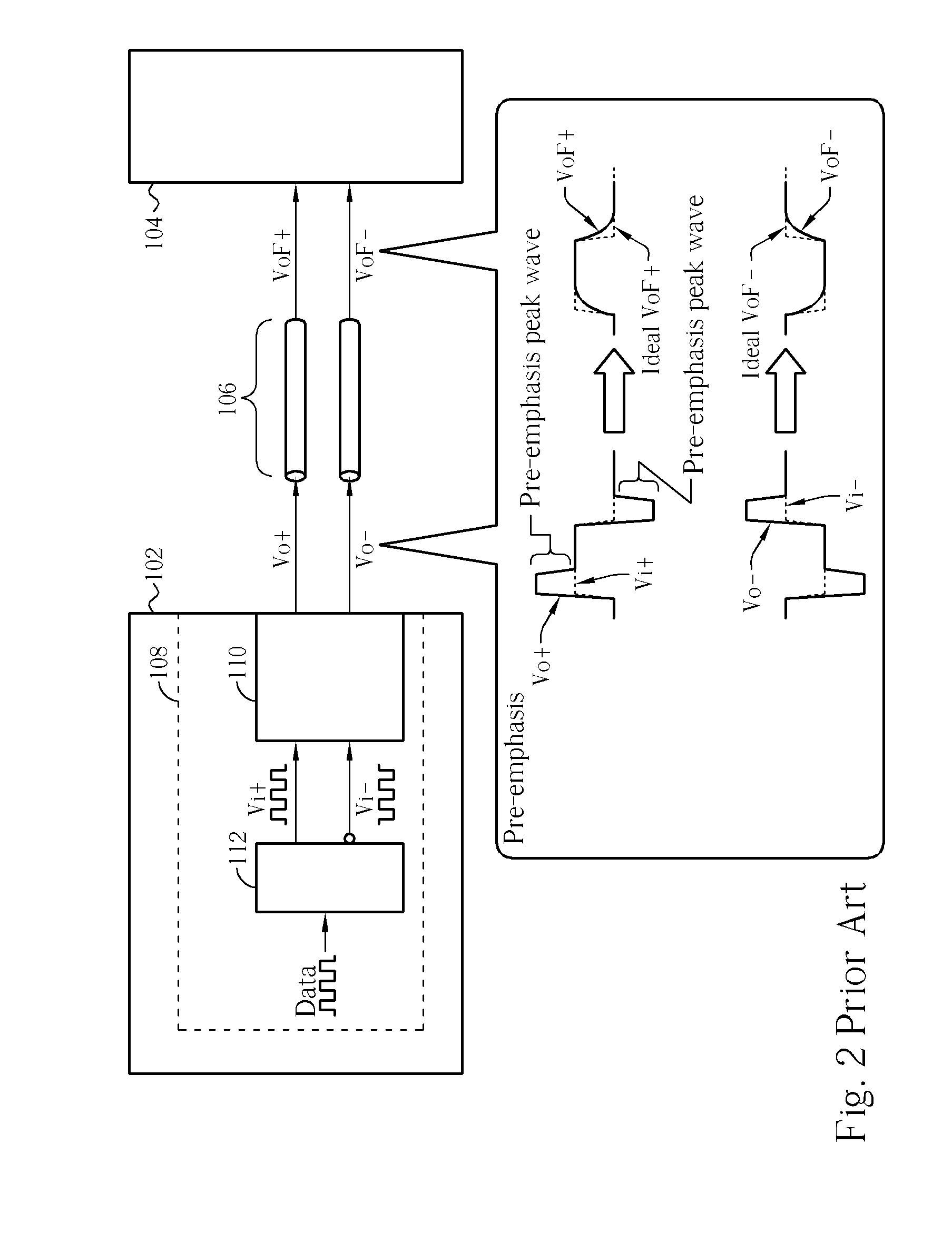
[0022]Please refer to FIG. 1, it shows that a transmission circuit 102 transmits data to a receiving circuit 104 in an electronic system 100. As people skilled in the art know, when transmitting data, it is better to resist noise and reduce the effects on other circuits by utilizing differential signals. Thus, in FIG. 1 and below, we discuss the related techniques of the present invention based on differential signal transmission. In the electronic system 100, in order to transmit data in the form of electronic signals to the receiving circuit 104, the transmission circuit 102 is equipped with an output circuit 108 including a transformation circuit 112 and a transmission circuit 110. The datum ready to transmit is taken as an input signal Data which is transformed into two differential signals Vi+ and Vi− by the transformation circuit 112, and the transmission circuit 110 outputs the differential signals Vo+ and Vo− in response to Vi+ and Vi−. The differential output signals Vo+ an...


PUM


Abstract

A transmission circuit and related method are disclosed. A transmitter in the transmission circuit has CMOS transistors as driving units for responding an input signal to drive an output signal at an output node, and each driving unit has a corresponding charge unit formed by a capacitor-connected MOS of a same type as that of the corresponding driving unit. Each charge unit is controlled by an auxiliary signal inverse to the input signal. When a level transition occurs in the input signal, the charge unit can compensate charge injection and clock feed-through caused by the driving unit at the output node, and form peaks for pre-emphasis. In this way, a better transmission property can be realized by using a simpler and low-power circuit design.

Description

BACKGROUND OF THE INVENTION [0001]1. Field of the Invention[0002]The present invention provides a transmission circuit and related method, and more particularly, a transmitter circuit and related method compensating and emphasizing the quality of the transmission signal with equivalent capacitance effect.[0003]2. Description of the Prior Art[0004]In modern society, every kind of information, such as data, documents, and video files are able to be transformed into electronic signals. How to quickly and correctly transmit electronic signals for information circulation with more efficiency has also become the target of the research and development of modern information companies. For instance, in the electronic systems or network systems, data exchanging between different functions of circuits, devices, and terminals is accomplished by buses or network transmission lines for coordinating the operation, which realizes the entire function of the electronic systems or the network systems....

Claims


Application Information

Patent Timeline
IPC IPC(8): H03G3/20
CPCH03K5/01H04L25/028H04L25/0272H03K5/151
Inventor LIU, CHIH-MIN
Owner VIA TECH INC
Why Eureka
Try Eureka