Method and a device for monitoring an/or controlling a load on a tensioned elongated element

a technology of tensioned elongated elements and methods, which is applied in the direction of drilling machines and methods, instruments, fluid removal, etc., can solve the problem of not being able to measure the declination or bending moment directly on the coiled tubing itself, and the problem of impracticality

Active Publication Date: 2007-08-02
VETCO GRAY SCANDINAVIA
View PDF15 Cites 15 Cited by
  • Summary
  • Abstract
  • Description
  • Claims
  • Application Information

AI Technical Summary

Benefits of technology

[0046] The effect on the coiled tubing declinations of a change in vessel position is determined by the following equations: sin⁢ ⁢αbv=KTTb⁢uvsin⁢ ⁢αtv=KTTt⁢uv

Problems solved by technology

However, because the coiled tubing most of the time during operation is either being inserted into the well or being retracted, it is considered impractical to measure the declination or bending moment at lubricator entry directly on the coiled tubing itself.

Method used


Image

  • Method and a device for monitoring an/or controlling a load on a tensioned elongated element
  • Method and a device for monitoring an/or controlling a load on a tensioned elongated element
  • Method and a device for monitoring an/or controlling a load on a tensioned elongated element

Examples


Embodiment Construction

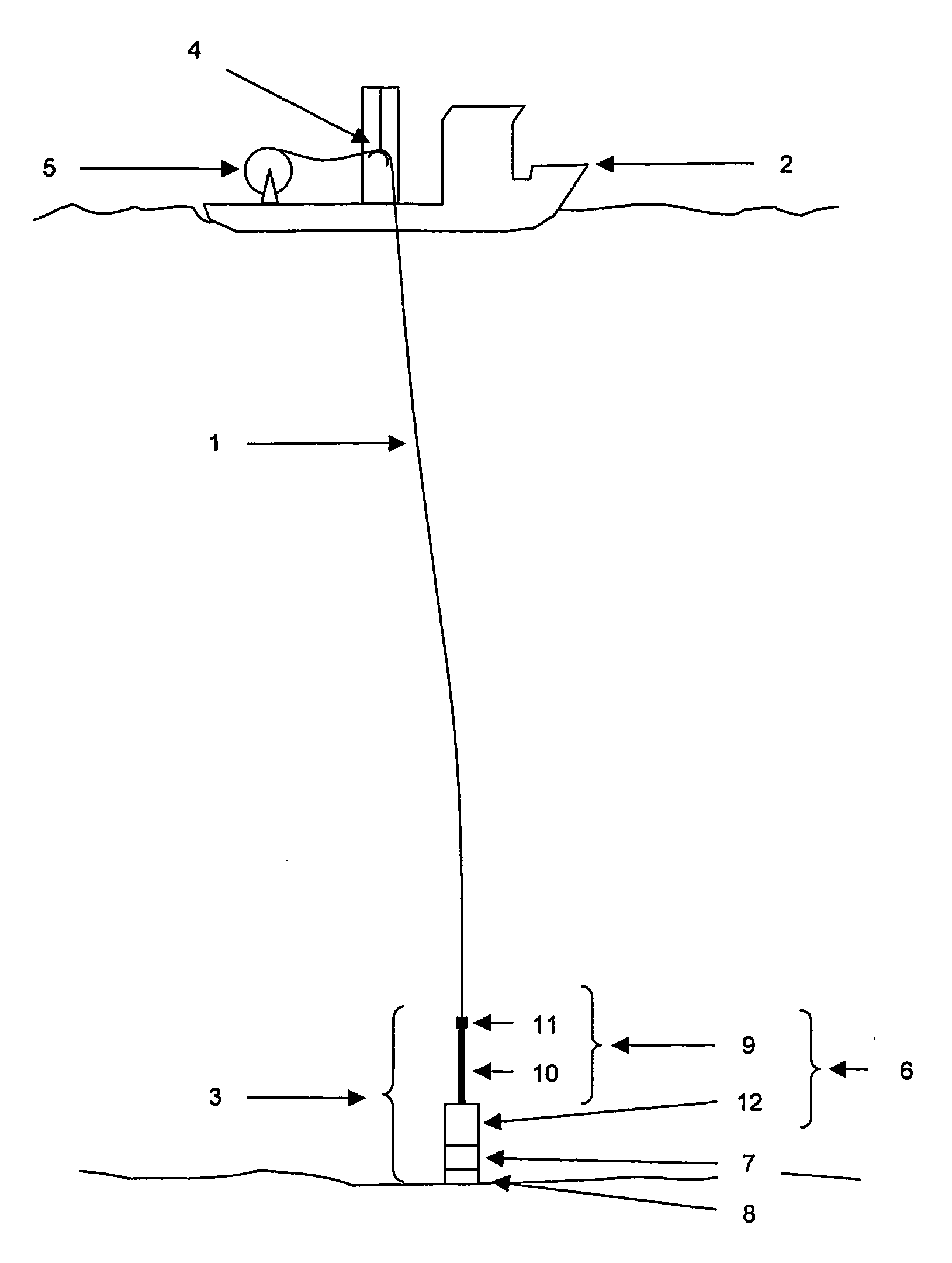
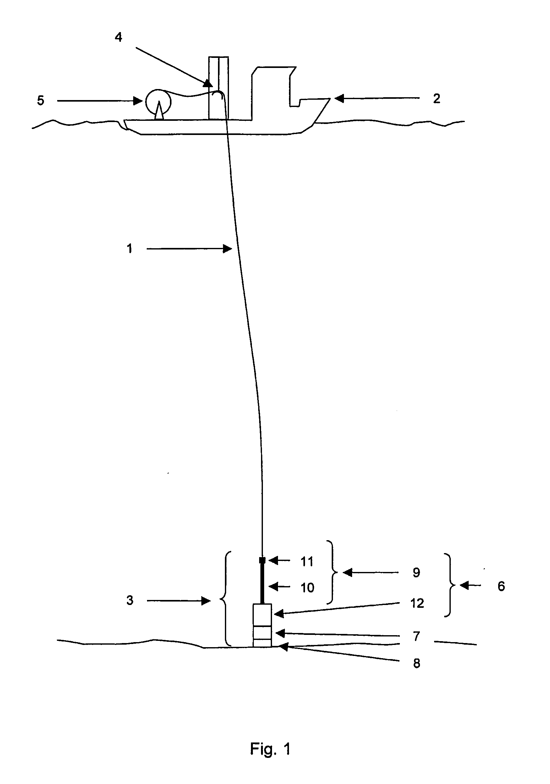
[0076]FIG. 1 shows a preferred system in which the inventive device for monitoring and / or controlling a load on a tensioned coiled tubing 1 is to be applied. A system corresponding to FIG. 1 has also been described in the International application no. PCT / IB2003 / 003084 (WO 2004 / 003338 A1), which hereby is included by reference in its entirety. The coiled tubing 1 extends from a dynamically positioned intervention vessel 2 through a water body mass in open sea down to a subsea wellhead assembly 3. For simplicity, FIG. 1 shows only the major components of the system focusing on the structural load carrying parts: coiled tubing 1, lubricator package 6 etc.

[0077] The system comprises the following main components: a coiled tubing surface system including a heave compensated coiled tubing suspension and tensioning system 4 and a coiled tubing reel 5 for feeding out / retracting coiled tubing; a surface handling and motion compensation system (not shown) for running and retrieval of equipm...


PUM


Abstract

A method and device for monitoring and/or controlling a load on a slender, tensioned elongated element extending from a subsea wellhead element to a surface vessel. The tensioned elongated element is arranged so as to be displaced in its longitudinal direction into or out of the subsea wellhead element via an entry at a top end of the latter. The structural behaviour of the wellhead element is measured. The bending moment and/or declination of the tensioned elongated element is estimated in a bottom region adjacent to and/or at the entry upon the basis of the measurement of the structural behaviour of the wellhead element.

Description

TECHNICAL FIELD [0001] The present invention relates to a method and a device for monitoring and / or controlling a load on a slender, tensioned elongated element extending from a sub-sea wellhead element to a surface vessel, by which the tensioned elongated element is arranged so as to be displaced in its longitudinal direction into or out of the sub-sea wellhead element via an entry at a top end of the latter. [0002] The tensioned elongated element may be any kind of tubing or cable, or even a beam. The wellhead element may be any kind of guiding element, preferably a guiding tube such as a lubricator pipe, that has a bending stiffness that is substantially higher than that of the tensioned elongated element. [0003] In particular, as will be described further in the description of the invention, the tensioned elongated element comprises coiled tubing, and the wellhead element comprises a lubricator means, especially a tube or pipe, via which the coiled tubing is forwarded into the w...

Claims


Application Information

Patent Timeline
Patent Type & Authority Applications(United States)
IPC IPC(8): E21B34/04E21B19/00
CPCE21B17/20E21B19/22E21B19/002
Inventor HOEN, CHRISTOPHER
Owner VETCO GRAY SCANDINAVIA
Why Eureka
Try Eureka