Portable vibratory screed with bubble vial inclination indication system

a vibratory screed and inclination indication technology, which is applied in the field of vibratory screeds, can solve the problems of requiring a great deal of skill and experience, affecting the operation of the operator, and reducing the responsiveness of the operator to manipulation, so as to reduce the risk of operator manipulation and reduce the risk of bending or bending

Inactive Publication Date: 2010-03-30
WACKER NEUSON PRODN AMERICAS
View PDF23 Cites 6 Cited by
  • Summary
  • Abstract
  • Description
  • Claims
  • Application Information

AI Technical Summary

Benefits of technology

[0009]The blade of the screed may be configured to minimize twisting or bending along its length. Such a construction provides for a substantially uniform and flat finished surface and also provides for high responsiveness to operator manipulation of the screed's handle. This effect is achieved by providing the blade with a cross-sectional shape that rigidities the screed. For instance, the blade may be generally b-shaped when seen in transverse cross section.

Problems solved by technology

Additionally, manually striking-off the concrete material is very labor intensive and requires a great deal of skill and experience to ensure a flat and properly inclined finished surface.
However, the isolation mechanism provides an undesirable response to handle movement during operation because the isolation mechanism distorts upon handle movement so that only a portion of the effect of the handle's motion is translated to the blade.
Accordingly, the isolation mechanism detrimentally affects the operator's ability to control the position of the blade.
However, many such systems fail to address the positioning of the handle, and thereby the pitch of the blade, relative to the bottom surface of the blade.
As such, such laser elevation systems are only somewhat successful at properly indicating to the operator the direction the handle should be moved to acquire an elevation and / or pitch that is consistent with the desired elevation.
Additionally, the laser elevation and inclination systems are costly to integrate into a screed.
From a manufacturing perspective, these costs are commonly deferred to the customer as well as the costs associated with the service and maintenance requirements of such systems.
However, as discussed in U.S. Pat. No. 6,758,631 the '631 patent, such indicators have been less than successful at indicating the inclination of the blade of the screed during operation of an exciter assembly.
That is, vibrations generated by operation of the exciter assembly propagate to the bubble vial and obliterate the bubble of the site level, rendering it useless.
The '631 patent concludes that bubble vials or site levels are unacceptable for screed inclination indication during screeding.

Method used


Image

  • Portable vibratory screed with bubble vial inclination indication system
  • Portable vibratory screed with bubble vial inclination indication system
  • Portable vibratory screed with bubble vial inclination indication system

Examples


Embodiment Construction

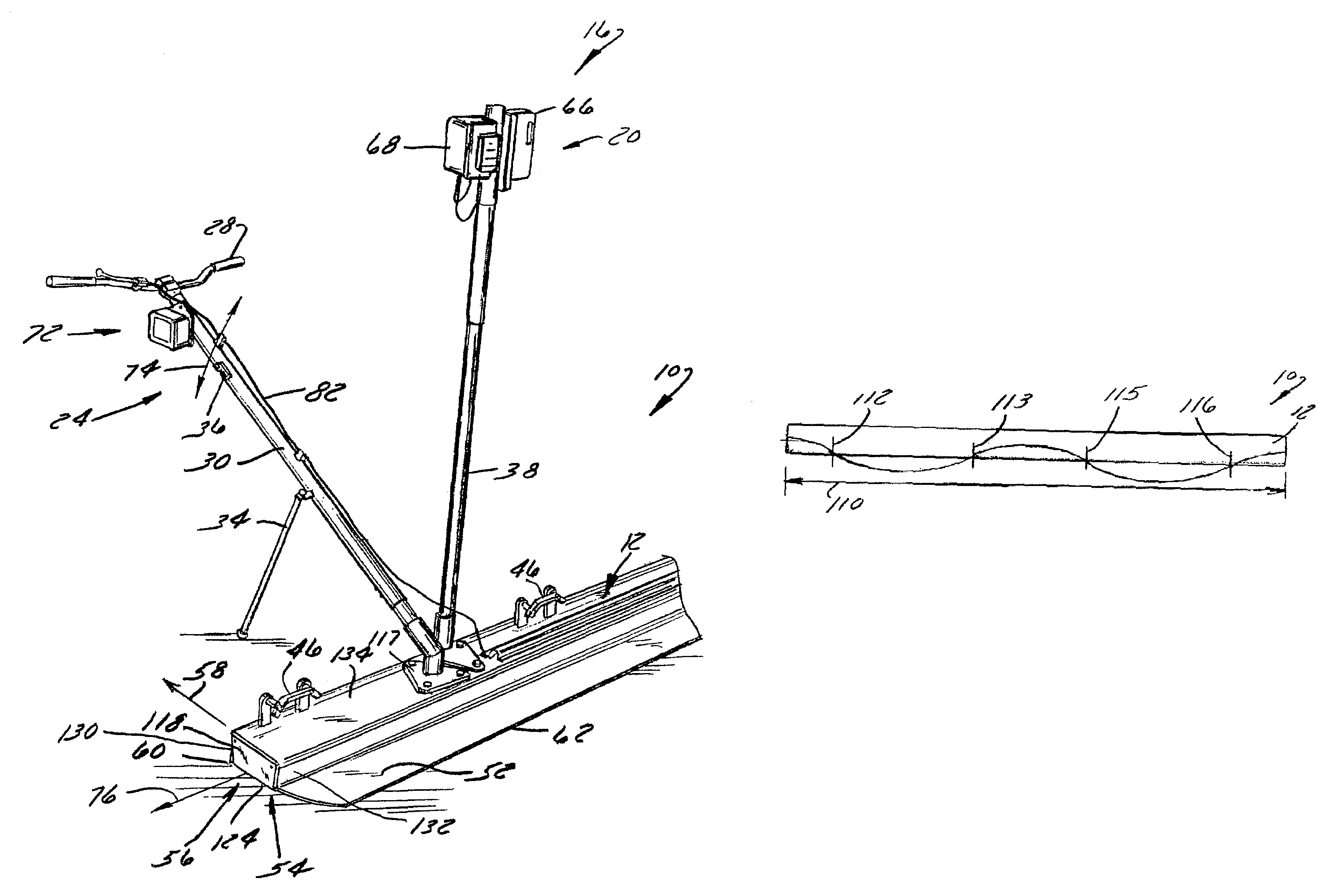
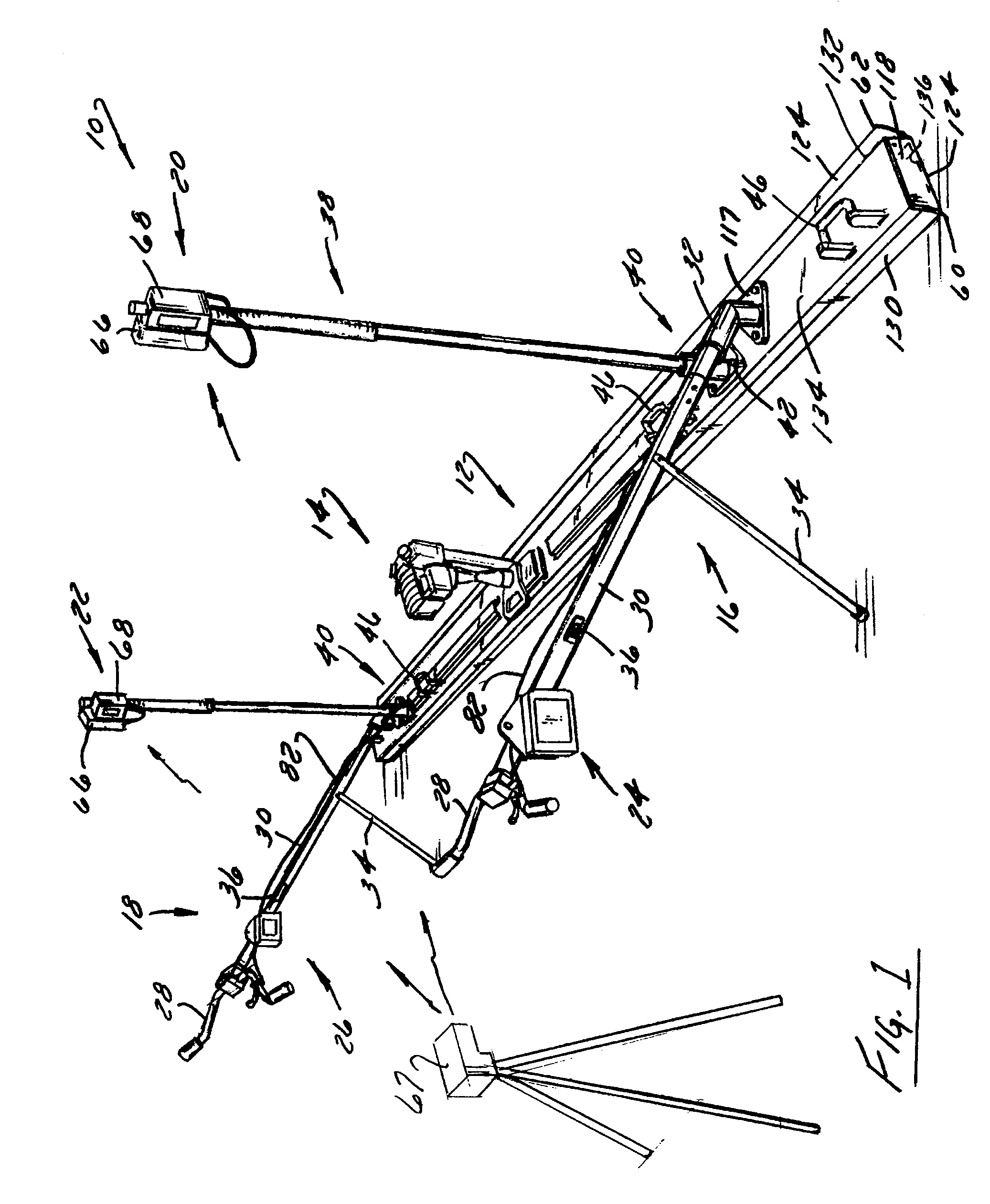
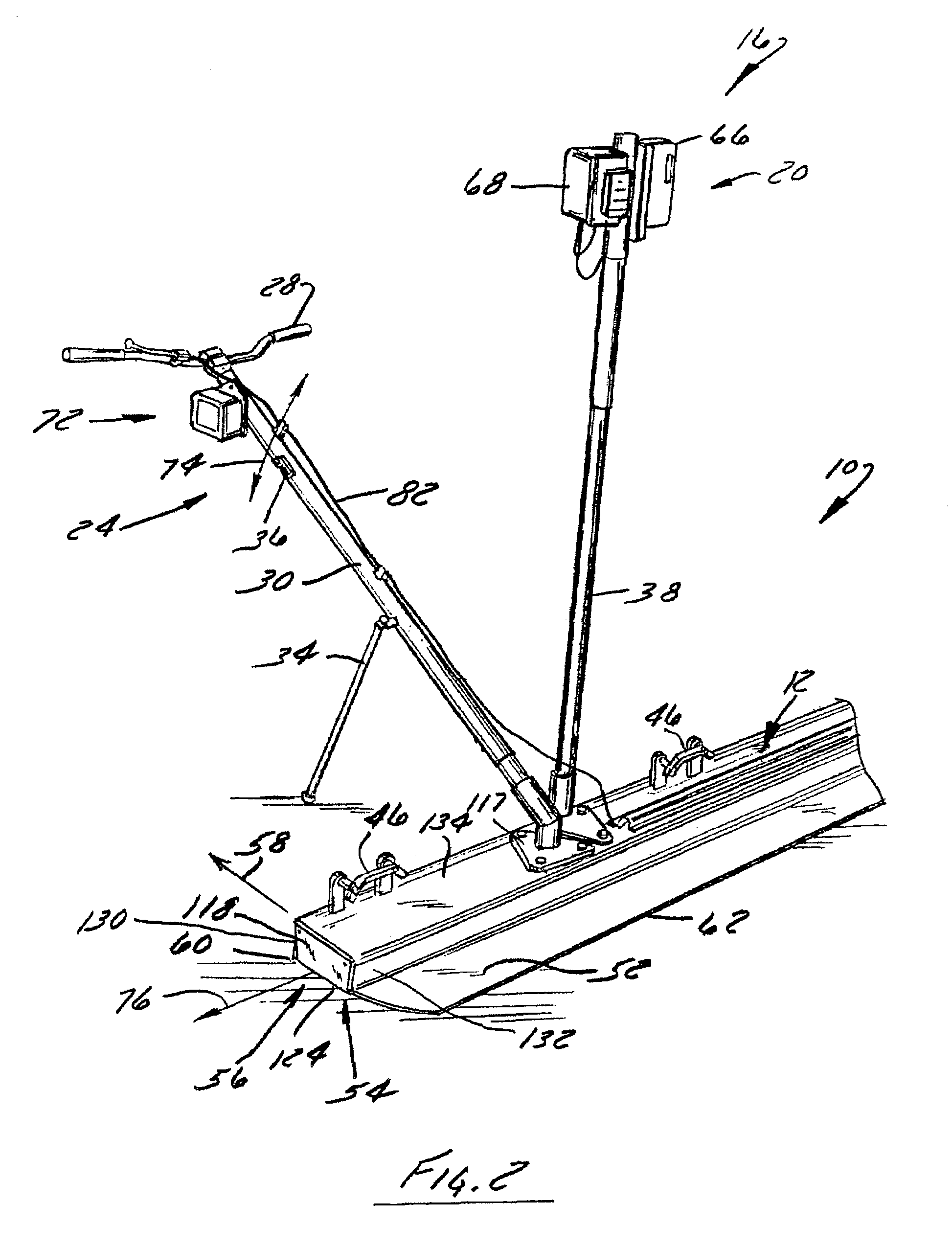
[0023]FIG. 1 shows a portable vibratory screed 10 according to a one embodiment of the present invention. Portable vibratory screed 10 includes a board or blade 12 having a vibration mechanism 14 attached thereto. A first operator station 16 and a second operator station 18 are connected to blade 12. In one embodiment, operation stations 16, 18 each include a laser leveling system 20, 22 and a handle assembly 24, 26. Understandably, although two operator stations are shown, screed 10 could be provided in a single operator configuration which would include a single handle assemble positioned proximate a lengthwise center of blade 12. Each handle assembly 24, 26 includes a handlebar 28 constructed to be engaged by an operator. A handle tube 30 extends between handlebar 28 and blade 12. The handle tube 30 is rigidly connected directly to the blade 12 by a handle mount bracket 32. A kickstand 34 is pivotably connected to each handle tube 30 and maintains portable vibratory screed 10 in ...


PUM


Abstract

A portable vibratory screed includes a blade that is connected to a handle constructed to be manipulated by an operator. Nodes of minimum vibrational amplitude are formed at specific locations along the length of the blade when the exciter is driven at a rated operating speed. A site level and / or the handle is attached to the blade at or in the vicinity of one or more of these nodes, therefore, is relatively isolated from induced vibrations.

Description

CROSS-REFERENCE TO RELATED APPLICATION[0001]This application claims priority to U.S. Provisional Patent Application Ser. No. 60 / 804,847, filed on Jun. 15, 2006 titled “Portable Vibratory Screed”, the disclosure of which is incorporated herein.FIELD OF THE INVENTION[0002]The present invention relates generally to screeds for leveling concrete, and more particularly, to a portable vibratory screed having vibration sensitive components, such as an economical inclination indication system and / or handles, positioned so as to be relatively immune to vibrations generated during screed operation. The screed may include a robust blade construction instead of or in addition to having vibration immunizing component positioning.BACKGROUND OF THE INVENTION[0003]During a concrete pouring process, a material that includes aggregates, cement, and water is poured into an area that may be bounded by forms to contain the concrete material. As concrete is delivered into the pour area, a plurality of la...

Claims


Application Information

Patent Timeline
Patent Type & Authority Patents(United States)
IPC IPC(8): E01C19/38
CPCE01C19/402
Inventor LUTZ, TODD J.GOLDBERG, RICHARD D.DAUFFENBACH, DARRIN W.LICKEL, TIMOTHY J.
Owner WACKER NEUSON PRODN AMERICAS
Why Eureka
Try Eureka