Vibration reduction apparatus for power tool and power tool incorporating such apparatus

Inactive Publication Date: 2008-08-07
BLACK & DECKER INC
View PDF20 Cites 6 Cited by
  • Summary
  • Abstract
  • Description
  • Claims
  • Application Information

AI Technical Summary

Benefits of technology

[0026]This provides the advantage of enabling a parallelogram li

Problems solved by technology

However, known hammer drills of this type suffer from the drawback that the hammer action generates signific

Method used


Image

  • Vibration reduction apparatus for power tool and power tool incorporating such apparatus
  • Vibration reduction apparatus for power tool and power tool incorporating such apparatus
  • Vibration reduction apparatus for power tool and power tool incorporating such apparatus

Examples


first embodiment

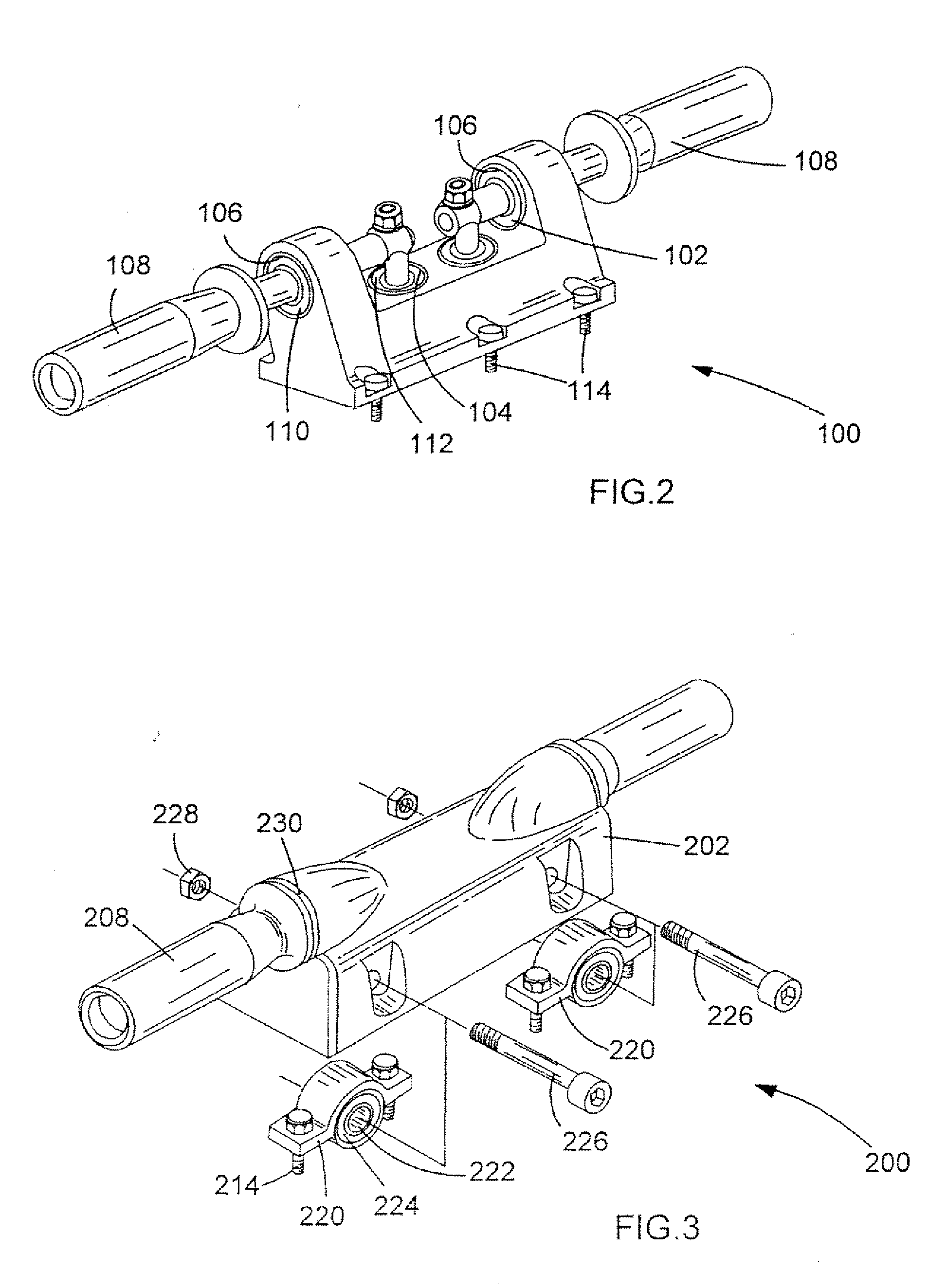
[0041]Referring to FIG. 2, a handle assembly 100 of the invention for use with a power hammer (not shown) has a body portion 102 having a pair of apertures 104 in a horizontal surface thereof, and a pair of apertures 106 through vertically extending portions thereof. A pair of handles 108 are mounted to the body portion 102 via apertures 104, 106, the gaps between the walls of apertures 104 and the handles 108 being occupied by vibration damping elastomeric material 112 and the gaps between the handles 108 and the walls of apertures 106 being filled with vibration damping elastomeric material 110. The body portion 102 is rigidly mounted to a housing (not shown) of the power hammer by means of a series of bolts 114.

[0042]Because the only mechanical connection between handles 108 and the housing of the power hammer is via two sets of vibration damping material 110, 112, each of which damps vibration in a direction not parallel to the other, the amount of vibration transmitted to a use...

second embodiment

[0043]Referring now to FIG. 3, in which parts common to the embodiment of FIG. 2 are denoted by like reference numerals but increased by 100, a handle assembly 200 of the present invention is mounted to a housing (not shown) of a power hammer by attaching brackets 220 to the housing via bolts 214. Each of the brackets 220 defines an aperture 222 accommodating vibration damping elastomeric material 224 and is received in a respective recess within body portion 202 and mounted thereto by means of bolts 226 passing through apertures 222 and corresponding nuts 228, such that the vibration damping material 224 occupies the gaps between bolts 226 and the walls of apertures 222. The handles 208 are connected to the body portion 202 by means of vibration damping elastomeric material 230 which act to damp vibrations along a direction generally at right angles to the direction of vibrations damped by elastomeric material 224. The present invention therefore also damps vibrations from the hous...

third embodiment

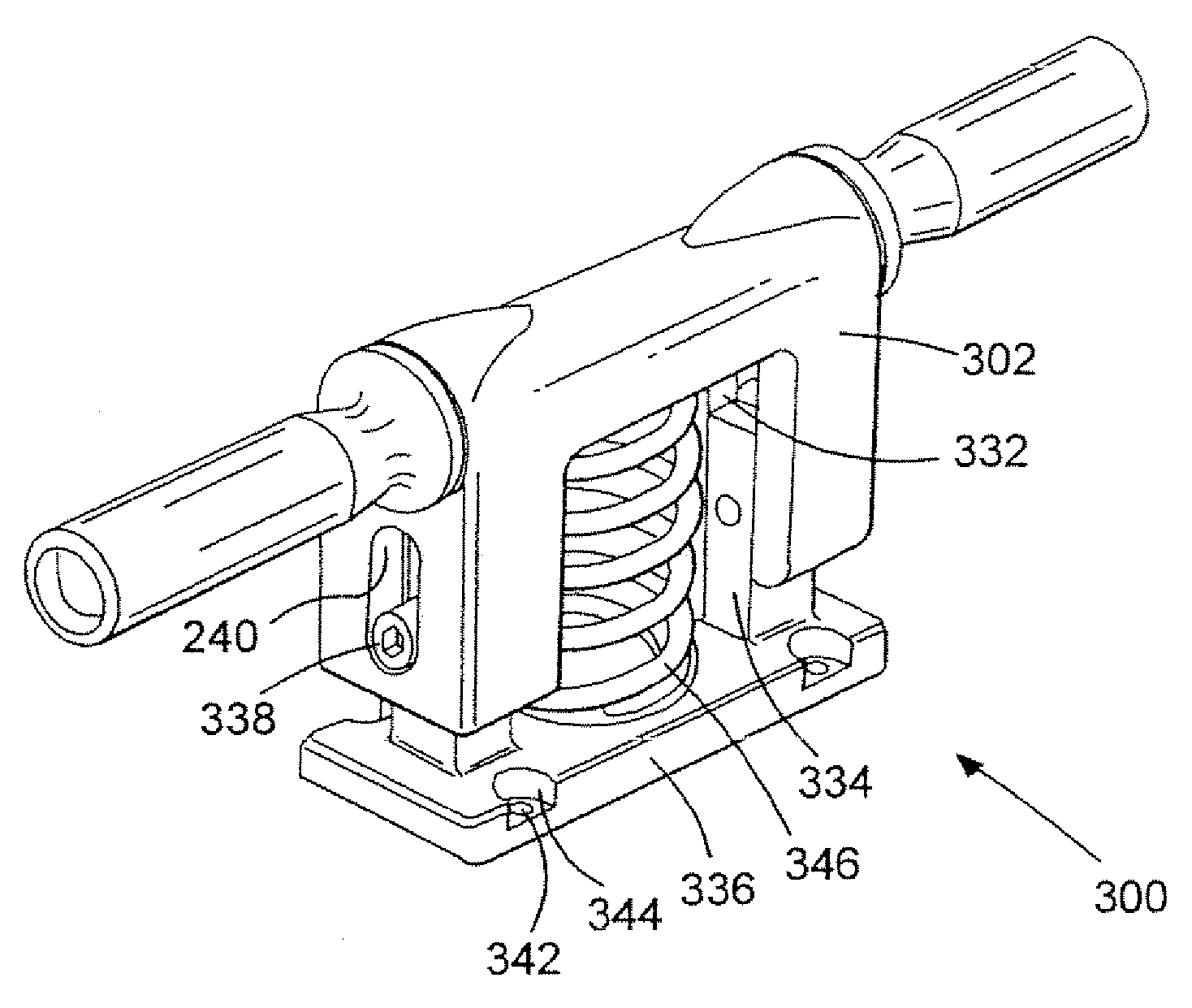
[0044]Referring now to FIG. 4, in which parts common to the embodiment of FIG. 3 are denoted by like reference numerals but increased by 100, a handle assembly 300 of the present invention has a body portion 302 having channels 332 on its underside to which columns 334 of a support 336 are attached by means of bolts 338 such that the body 302 can slide vertically relative to the support 336 by an amount limited by the length of slots 340. The support 336 is attached to a housing of the power hammer by means of bolts (not shown) which fit within holes 342 located in recesses 344. The body portion 302 and support 336 are urged apart by means of a compression spring 346.


PUM


Abstract

A handle assembly for a power tool, the handle assembly comprising:- attachment means for attaching the assembly to a housing of a power tool; handle means adapted to be held by a user of the power tool, wherein the handle means is mounted to said attachment means and is capable of limited movement relative to the housing of the power tool; and vibration damping means acting between said housing and said handle means. The vibration damping means can comprise elastomeric material. The attachment means can be mounted in use to the housing via a bolt on one of the attachment means and the housing passing through a respective aperture in the other of said attachment means and the housing, wherein at least some of the elastomeric material is arranged in use between at least one said bolt and a corresponding said aperture. The handle means can be pivotable and/or slidable relative to said attachment means. The vibration damping means can comprise at least one spring eg. compression/spring or torsion.

Description

FIELD OF THE INVENTION[0001]The present invention relates to a vibration reduction apparatus for a power tool and to a power tools incorporating such apparatus. The invention relates particularly, but not exclusively, to vibration reduction apparatus for powered hammers, and to hammers incorporating such apparatus.BACKGROUND OF THE INVENTION[0002]Electrically driven hammers are known in which a driving member in the form of a flying mass is reciprocally driven in a piston, and impact of the flying mass against the end of the piston imparts a hammer action to a bit of the hammer. Such an arrangement is disclosed in European patent application EP1252976 and is shown in FIG. 1.[0003]Referring in detail to FIG. 1, the prior art demolition hammer comprises an electric motor 2, a gear arrangement and a piston drive arrangement which are housed within a metal gear housing 5 surrounded by a plastic housing 4. A rear handle housing incorporating a rear handle 6 and a trigger switch arrangeme...

Claims


Application Information

Patent Timeline
IPC IPC(8): B25D17/24B25D17/00B23B45/16B25D17/04
CPCB25D17/043
Inventor BECHT, REIMUNDHAHN, NORBERTSTIRM, MICHAELSEEBAUER, RALF
Owner BLACK & DECKER INC
Why Eureka
Try Eureka