Gasket with spring collar for prosthetic heart valves and methods for making and using them

a heart valve and spring collar technology, applied in the field of multi-component heart valve assemblies, can solve the problems of difficult to achieve the effect of enhancing the fluid flow or other performance characteristics of the implanted heart valve assembly, and the difficulty of ensuring the spring collar within the target site,

Active Publication Date: 2007-08-02
MEDTRONIC INC
View PDF48 Cites 115 Cited by
  • Summary
  • Abstract
  • Description
  • Claims
  • Application Information

AI Technical Summary

Benefits of technology

[0018] The collar may support the prosthetic valve above the tissue biological, e.g., within the sinus cavity, e.g., the sinus of Valsalva above an aortic valve site. In addition or alternatively, the collar may allow the prosthetic valve to have a larger size than the annular member, thereby enhancing the fluid flow or other performance characteristics of the implanted heart valve assembly. Optionally, the collar may include a funnel or other tapered shape that may provide a transition from a relatively larger prosthetic valve to the annular member within the biological annulus. In addition, the collar may support the prosthetic valve away from a wall of the sinus or other supra-annular space, while still allowing blood to flow easily into the coronary arteries around the prosthetic valve.

Problems solved by technology

The sewing rings of either type of prosthetic valve can be tedious and time consuming to secure within a target site, i.e., within an annulus of a heart where a natural heart valve has been removed.
Consequently, this procedure can be very complicated, requiring management and manipulation of many sutures.
The complexity of the procedure also provides a greater opportunity for mistakes and requires a patient to be on cardiopulmonary bypass for a lengthy period of time.
Because the annulus of the heart may not match the circular cross-section of the sewing ring and / or prosthetic valve, the prosthetic valve may not fit optimally within the annulus.
As a result, natural blood hemodynamics through and around the valve may be impaired, resulting in clotting, possible emboli production, and eventual calcification of the valve structure.
When a mechanical or other prosthetic valve is then attached to the sewing ring, however, the valve and sewing ring may not mate together effectively, e.g., if the shape of the sewing ring has been distorted to conform to the annulus, which may also impair natural blood hemodynamics, create leaks, and / or otherwise impair performance of the prosthetic valve.

Method used


Image

  • Gasket with spring collar for prosthetic heart valves and methods for making and using them
  • Gasket with spring collar for prosthetic heart valves and methods for making and using them
  • Gasket with spring collar for prosthetic heart valves and methods for making and using them

Examples


Embodiment Construction

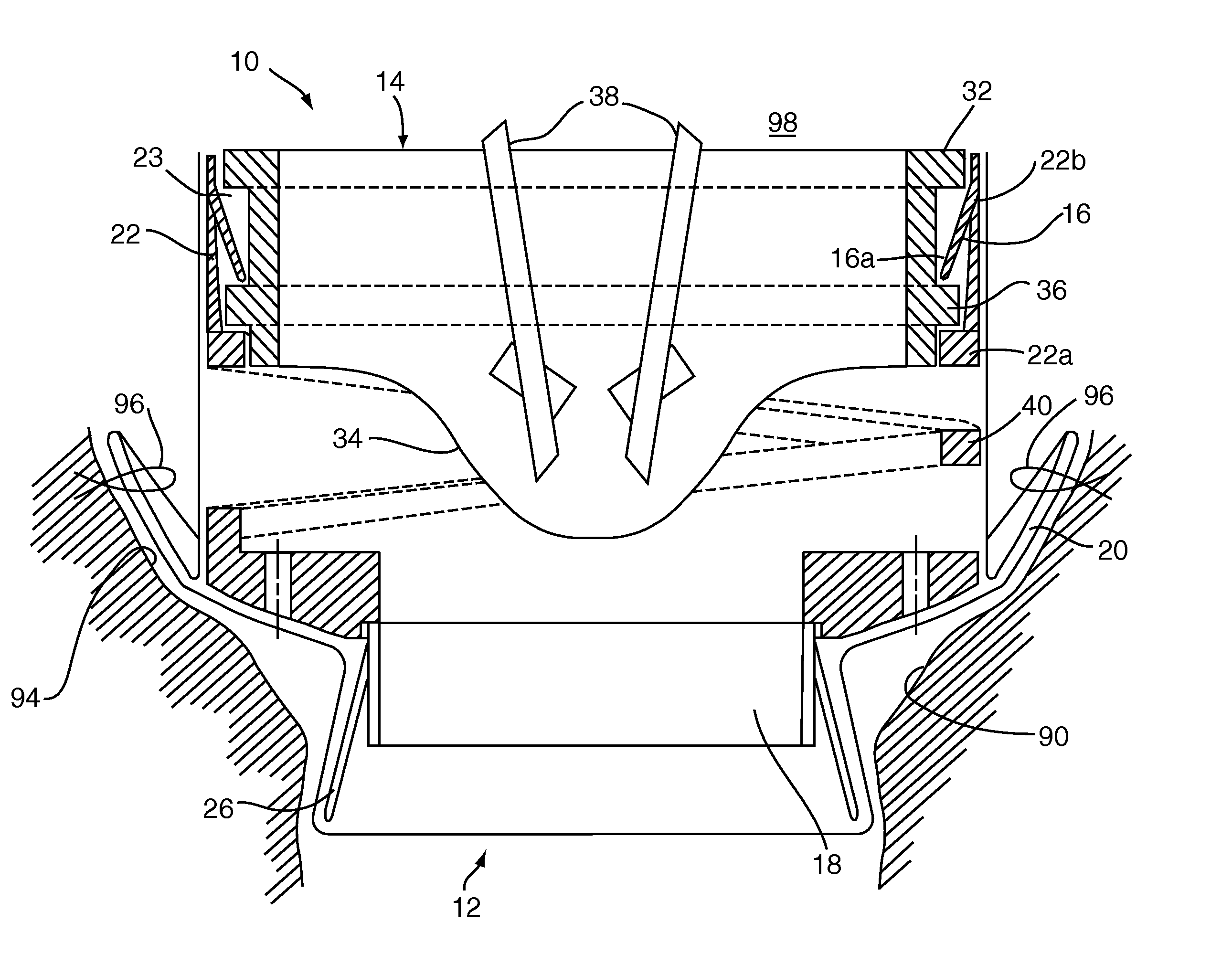
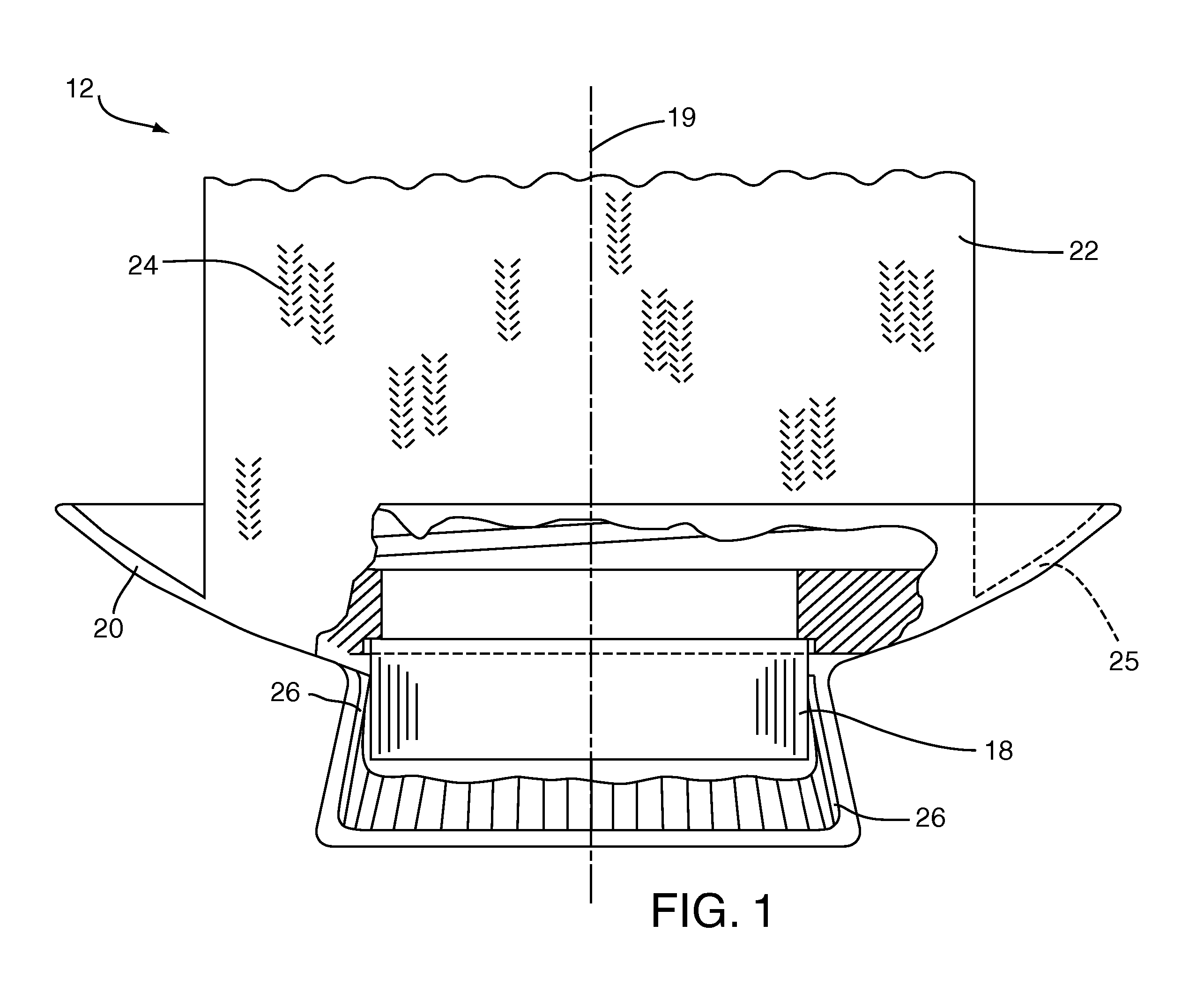
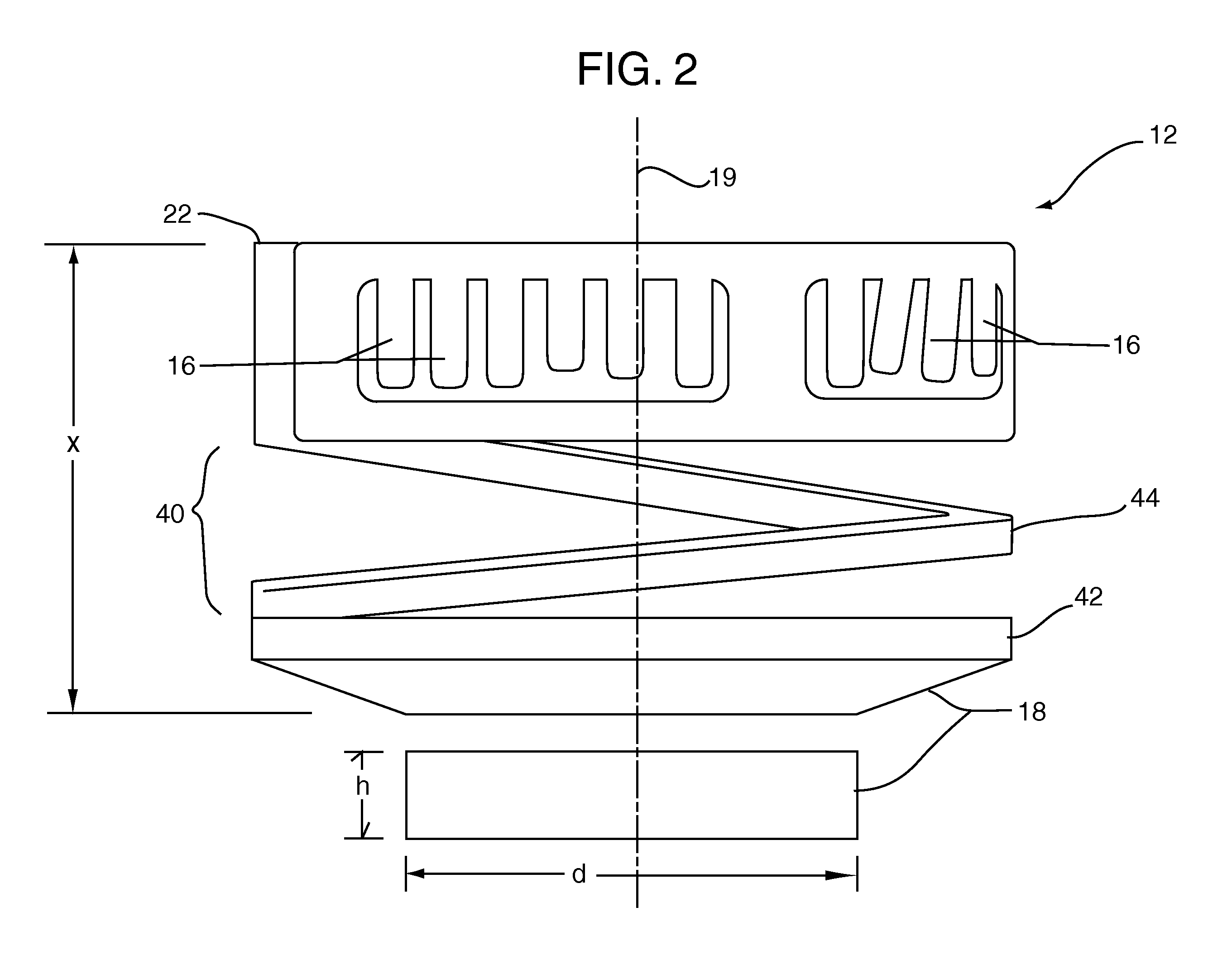
[0028] Turning to the drawings, FIGS. 1-5 show an exemplary embodiment of a heart valve assembly 10 that generally includes a gasket member 12 and a valve member 14. Generally, the gasket member 12 includes an annular ring 18, a sewing ring 20 extending radially from the annular ring 18, and a collar 22 extending upwardly from the annular ring 18. The valve member 14 may be a prosthetic valve, e.g., a mechanical or bioprosthetic valve, that may be secured to the collar 22 and / or other portion of the gasket member 12, e.g., after implanting the gasket member 12 within a tissue annulus, as described further elsewhere herein.

[0029] Turning to FIGS. 4 and 5, the valve member 14 may be a mechanical valve including an annular frame 32 supporting a pair of valve members 38 (shown in FIG. 5) that open and close within the frame 32. Optionally, the valve member 14 may include a pair of ears 34 extending downwardly from the frame 32, e.g., for pivotally supporting the valve members 38. In an...


PUM


Abstract

A heart valve prostheses includes an annular member implantable within a biological annulus, a collar extending upwardly from the annular member, and a sewing ring extending from the annular member. A spring structure couples the collar to the annular member and biases the collar to align with the annular member at a predetermined distance above the annular member. During use, the prosthesis is introduced into a biological annulus, and fasteners are directed through the sewing ring into surrounding tissue to secure the prosthesis with the annular member within the biological annulus. A mechanical or bioprosthetic valve is introduced and coupled to the collar, e.g., using tabs or other connectors on the collar. The spring structure allows the collar to be directed towards the annular member and/or folded inwardly, e.g., to facilitate accessing the sewing ring to deliver fasteners.

Description

RELATED APPLICATION DATA [0001] This application claims benefit of provisional application Ser. No. 60 / 743,185, filed Jan. 27, 2006, the entire disclosure of which is expressly incorporated herein by reference.FIELD OF THE INVENTION [0002] The present invention relates generally to heart valves that may be implanted within a patient, and, more particularly, to multiple component heart valve assemblies, and to apparatus and methods for making and using them. BACKGROUND [0003] Prosthetic heart valves can replace defective human valves in patients. For example, one piece valves have been suggested that include sewing rings or suture cuffs that are attached to and extend around the outer circumference of a prosthetic valve. In addition, multiple component valves have also been suggested that include a sewing ring that is separate from a valve component. The sewing rings of either type of prosthetic valve can be tedious and time consuming to secure within a target site, i.e., within an a...

Claims


Application Information

Patent Timeline
Patent Type & Authority Applications(United States)
IPC IPC(8): A61F2/24
CPCA61F2250/006A61F2/2409
Inventor LANE, ERNEST
Owner MEDTRONIC INC
Why Eureka
Try Eureka