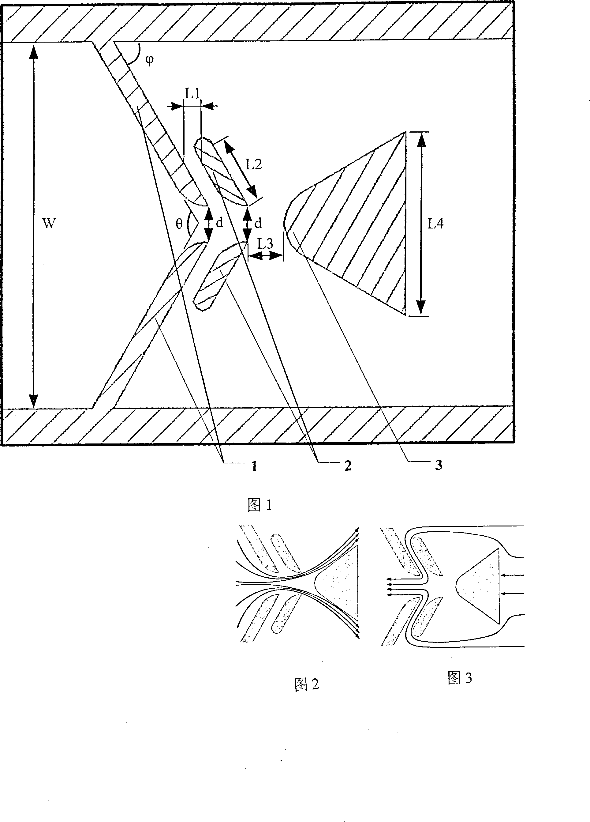
Three-rib type micro pneumatic valve

A pneumatic valve and three-rib technology, applied in the direction of fluid flow, mechanical equipment, etc., can solve the problems of low efficiency and increase of dynamic passive valves, and achieve the effects of low cost, long life and improved efficiency

Inactive Publication Date: 2008-05-28
NANJING UNIV OF AERONAUTICS & ASTRONAUTICS
View PDF0 Cites 3 Cited by
  • Summary
  • Abstract
  • Description
  • Claims
  • Application Information

AI Technical Summary

Problems solved by technology

[0004] The purpose of the present invention is to overcome the defect of low efficiency of the dynamic passive valve, and propose a three-rib micro-pneumatic valve that can be applied to the micro-jet device to control the flow direction and flow size of the fluid, and suppress the reverse flow through the new principle of fluid mechanics , so as to increase the forward and reverse flow difference to significantly improve the efficiency, thereby improving the application effect of the micro-fluidizer

Method used


Image

  • Three-rib type micro pneumatic valve

Examples


Embodiment

[0020] First, copper is used as the electrode material, and the electrode shown in Figure 5 is obtained through the wire cutting process. Then, the duralumin is used as the structural material, and the three ribs shown in Figure 6 are obtained by the EDM process. Type miniature pneumatic valve. The size of each part is specified as follows according to the proportions in the specific implementation manner:

[0021] The width d of the first and second rib nozzles is 1mm, the internal width W of the micro-valve is 10mm, the convergence angle θ of the first and second rib is 120 degrees, the angle φ between the downstream inclined wall of the first rib 1 and the horizontal wall is 60 degrees. The radius R1 of the transition arc segment of the primary rib 1 is 1mm, the central angle α1 of the transition arc segment of the primary rib 1 is 60 degrees, the horizontal distance L1 between the primary rib 1 and the secondary rib 2 is 0.3 mm, and the secondary rib 2 is inclined The len...


PUM


Abstract

The invention relates to a three-rib type minisize air-operated valve for controlling the flow direction and the flow of liquid. The structure is that a first level rib, a second level rib and a third level rib are arranged in the order from left to right to form the three-rib type minisize air-operated valve, wherein the first level rib is constituted by an upper part and a lower part which are symmetrical, and is positioned on the left end of the minisize valve. The second level rib is constituted by an upper part and a lower part which are symmetrical, and is positioned on the right side of the first level rib, and the second level rib is parallel with the first level rib, and the left apical angle of the third level rib is located on the right end of the minisize valve. The invention has the advantages that the three-rib type minisize air-operated valve controls counter flow through a novel fluid dynamics principle, the flow difference between forward direction and negative direction is increased, the fluid flow quantity transferred by a minisize ejector such as a micro pump is significantly increased, and the efficiency is increased to four times of a dynamic passive valve, and the invention has high reliability, long service life, easy processing, and low costs. The invention provides a micro flow system control device which has favorable comprehensive performance for military or civil places comprising the fields of aviation, space fight, medical treatment and automobile and the like.

Description

technical field [0001] The invention relates to a three-rib type micro-pneumatic valve, which is used for controlling the flow direction and flow rate of fluid, and belongs to the technical field of control devices for micro-flow systems. Background technique [0002] In recent years, with the rapid development of microelectromechanical systems, microfluidic systems, and microfabrication technologies, microfluidizers represented by micropumps and synthetic jets have not only been successfully used in microinjection, microjet printing, drug microdispensing, microfluidics Component heat dissipation, etc. (see Woias P, "Micropumps-summarizing the first two decades"), Proceedings of SPIE, 2001, Vol. 4560, No. 39 -52 pages); see Bratter R L, "Commercial success in the MEMS marketplace", Proceedings of Optical MEMS '2000, 29-30), and has broad application prospects in the fields of DNA separation and transport, active flow control, micro-aircraft and micro-satellite propulsion (s...

Claims


Application Information

Patent Timeline
Patent Type & Authority Applications(China)
IPC IPC(8): F15D1/02
Inventor 廖文和王鑫黄国平
Owner NANJING UNIV OF AERONAUTICS & ASTRONAUTICS
Why Eureka
Try Eureka