Regenerative media filtration

a technology of regenerative media and filter elements, applied in the field can solve the problems of inefficient placement of filtration elements, inefficient tank geometry, and negative impact on filtration efficiency, so as to improve the structure of regenerative media filter elements and achieve high fluid flow.

Active Publication Date: 2019-09-26
BLUE SKIES GLOBAL LLC
View PDF9 Cites 3 Cited by
  • Summary
  • Abstract
  • Description
  • Claims
  • Application Information

AI Technical Summary

Benefits of technology

[0008]To accomplish the foregoing and other objects, features and advantages of the present invention there is provided an improved regenerative media filter structure and associated method of manufacturing such a regenerative media filter, while solving the above mentioned problems associated with present regenerative media filter constructions. The present invention solves the problem by achieving high fluid flows unaffected by turbulence that plagues the current state-of-the-art of regenerative media filtration.
[0009]For the present invention the same end-use regenerative media filter will filter a greater volume of fluid in a substantially reduced volumetric footprint. The economy of filter size translates into the installation in previously height-restricted areas. This height reduction translates to a lower influent and effluent connection height which translates to pump head pressure reduction; thus translating into filtration energy savings presently unachievable due to the additional height of the prior art regenerative media filters.
[0012]In accordance with the present invention as described herein there is also provided numerous embodiments which are presented as having varying element profiles, lengths, and planar spacing, which when combined with the appropriate regenerative media will maintain the highest levels of regenerative media filtration while minimizing the filter height and / or filter width profile.
[0014]In accordance with other aspects of the present invention the bridging element or member includes at least three bridging elements that form, with three adjacent filter elements, the closed interstitial space; each filter element may be circular in cross-section; the closed interstitial space has three sides as defined by the bridging elements or members; the filter element may be a single layer filter element or a double layer filter element; including a coil spring that is disposed within the filter element, and wherein the array is formed in a honeycomb pattern; and wherein the coil spring comprises a compression spring wound helix that may be pre-compressed to maintain a taught sheath and prevent differential pressure collapse as the filter element becomes loaded with filtrate, and nominally has a wound diameter with staggered or equally spaced larger.

Problems solved by technology

The field of regenerative media filters suffers from inefficient placement of the filtration elements relative to each other.
The tank geometry is therefore overly sized and inefficient.
Furthermore, this inefficient placement makes the filter susceptible to turbulence, which negatively affects the filtration efficiency.

Method used


Image

  • Regenerative media filtration
  • Regenerative media filtration
  • Regenerative media filtration

Examples


Embodiment Construction

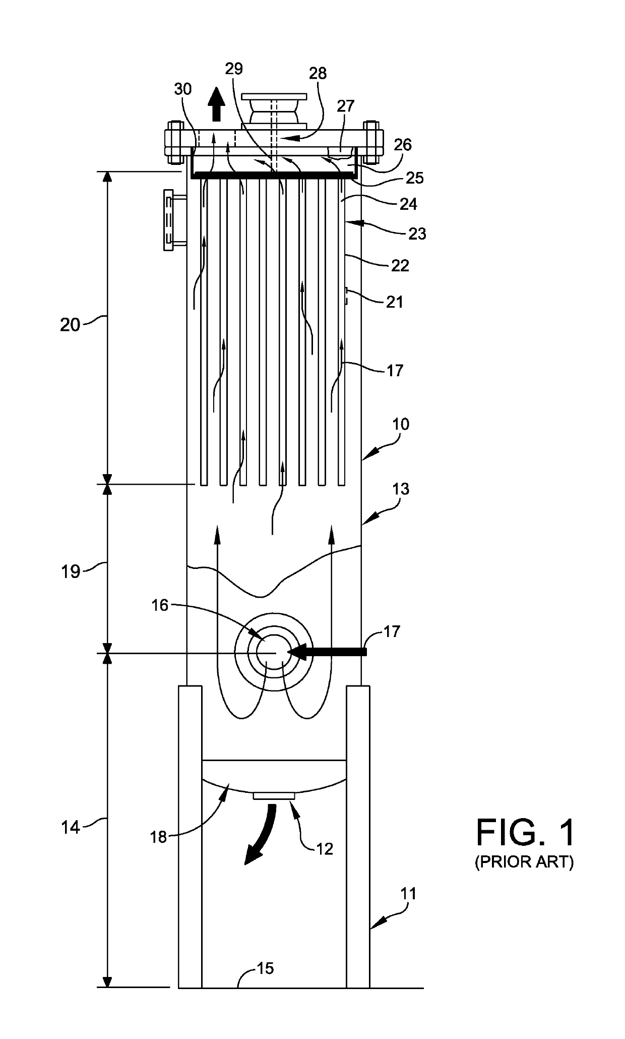
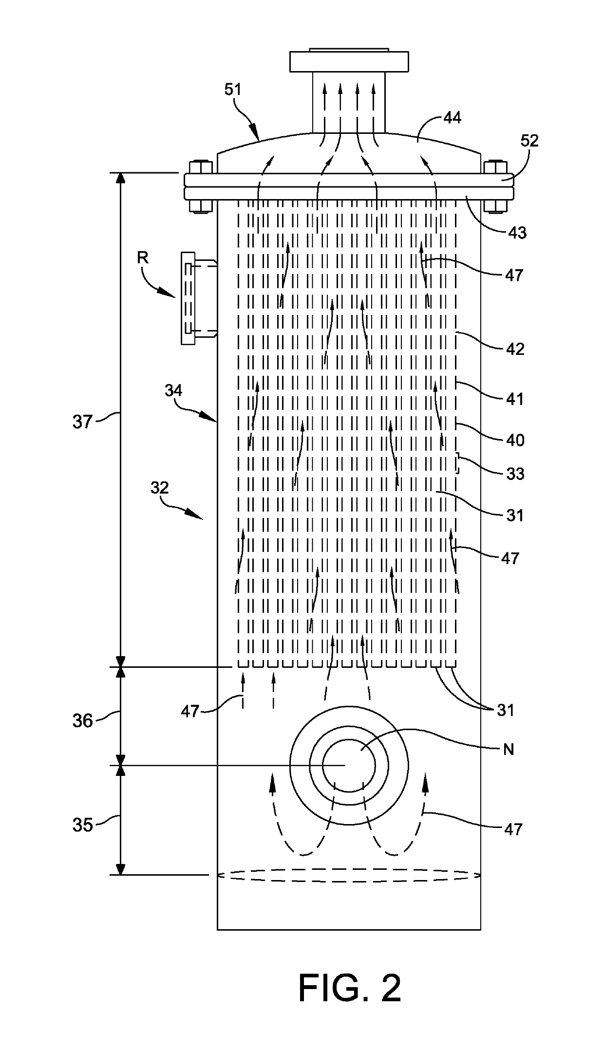
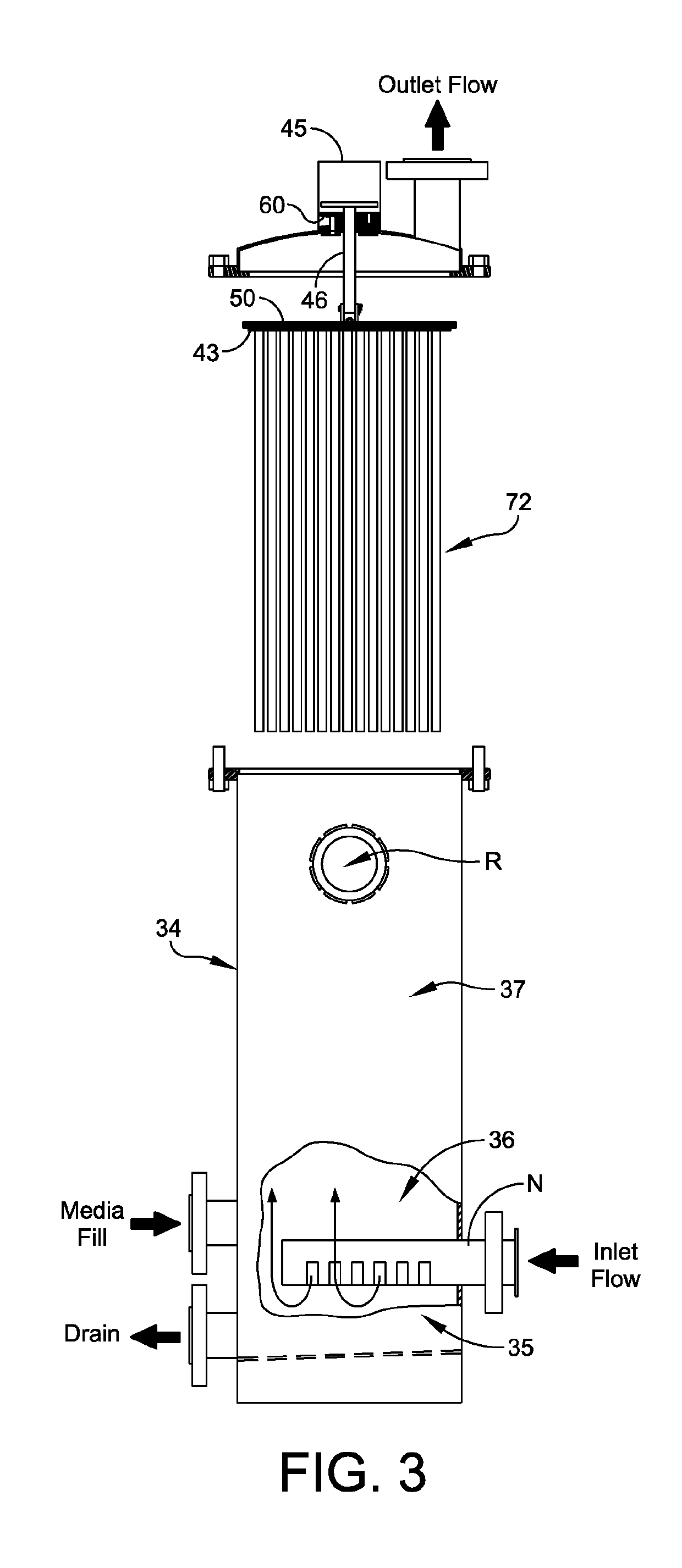
[0071]In accordance with the present invention the regenerative media filter is constructed to optimize the overall size of the filter per unit of fluid filtered and achieves this by optimizing multiple variables simultaneously, Refer in particular to FIG. 2 that illustrates a regenerative media filter in accordance with the present invention indicated generally at 32. These variables include, among possible other variables, the diameter of the filter elements 31; the planar spacing of the elements 31; the volume of regenerative media 33 that is deposited on the outer surface 40 of the filter elements 31; the resultant interstitial free space S (refer, for example, to the embodiment shown in FIG. 25) when the filter elements 31 are coated with the filtration media 33; the shell diameter of the filter housing 34; the height and volume of the inlet zone 35; the height and volume of the buffer zone 36; and the height and volume of the filtration zone 37 of the regenerative media filter...


PUM

PropertyMeasurementUnit
lengthaaaaaaaaaa
widthaaaaaaaaaa
surface areaaaaaaaaaaa

Abstract

A regenerative filter that includes a filter housing having inlet and outlet zones; a fluid path provided between the inlet and outlet zones; a plurality of filter elements each having an outer surface filter media applied thereto and functioning to filter particulate or contaminants from the fluid path; and a tube sheet that is supported across the filter housing, that is disposed just before the outlet zone and that provides the support for the plurality of filter elements. The plurality of filter elements are disposed in an array and includes bridging members or elements that connect between adjacent filter elements, and that forms with the filter elements, a closed interstitial space between adjacent filter elements for liquid flow; a nanoscale barrier on interior surfaces, including that of the regenerative media itself, providing a mechanism to disrupt the cell wall of microscopic viruses and organisms.

Description

RELATED CASES[0001]Priority for this application is hereby claimed under 35 U.S.C. § 119(e) to commonly owned and co-pending U.S. Provisional Patent Application Nos. 62 / 647,006 filed Mar. 23, 2018 and 62 / 655,468 which was filed on Apr. 10, 2018, and each of which is incorporated by reference herein in its entirety.FIELD OF THE INVENTION[0002]The present invention relates in general to improvements in subcomponents that form a regenerative media filter; particularly subcomponents within the gas and liquid filtration housing of the regenerative media filter. More particularly, the present invention relates to an improvement and optimization of the construction of interdependent components of the regenerative media filter. Even more particularly the present invention relates to the relative proximity and sizing of individual filter elements or components including the provision, in one embodiment, of a monolithic honeycomb-type filtration structure. The improved structure of the presen...

Claims


Application Information

Patent Timeline
Patent Type & Authority Applications(United States)
IPC IPC(8): B01D29/52B01D37/02B01D29/17
CPCB01D2201/0484B01D37/02B01D29/17B01D2201/0423B01D29/52B01D2201/0461B01D2201/0446B01D29/15B01D29/90
Inventor NEHLEN, III, PAUL F.
Owner BLUE SKIES GLOBAL LLC
Why Eureka
Try Eureka