Cable Interface

Inactive Publication Date: 2007-08-16
MONSTER
View PDF5 Cites 15 Cited by
  • Summary
  • Abstract
  • Description
  • Claims
  • Application Information

AI Technical Summary

Benefits of technology

[0006] A problem has arisen in HDMI technology where a digital signal is required to traverse a long distance. The bandwidth required to display SXGA is 83 MHZ. If a greater resolution, such as for HDTV, is desired, the bandwidth requirement will be correspondingly larger. If standard nineteen conductor cable is used, the crosst

Problems solved by technology

A problem has arisen in HDMI technology where a digital signal is required to traverse a long distance.
If standard nineteen conductor ca

Method used


Image

  • Cable Interface
  • Cable Interface
  • Cable Interface

Examples


Example

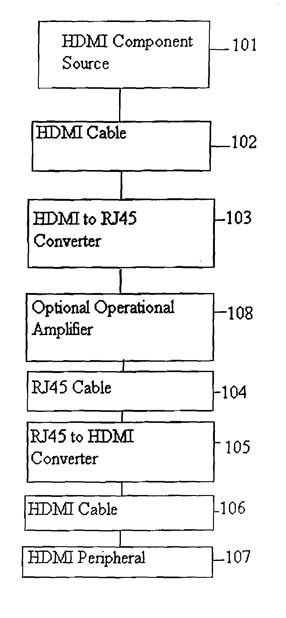
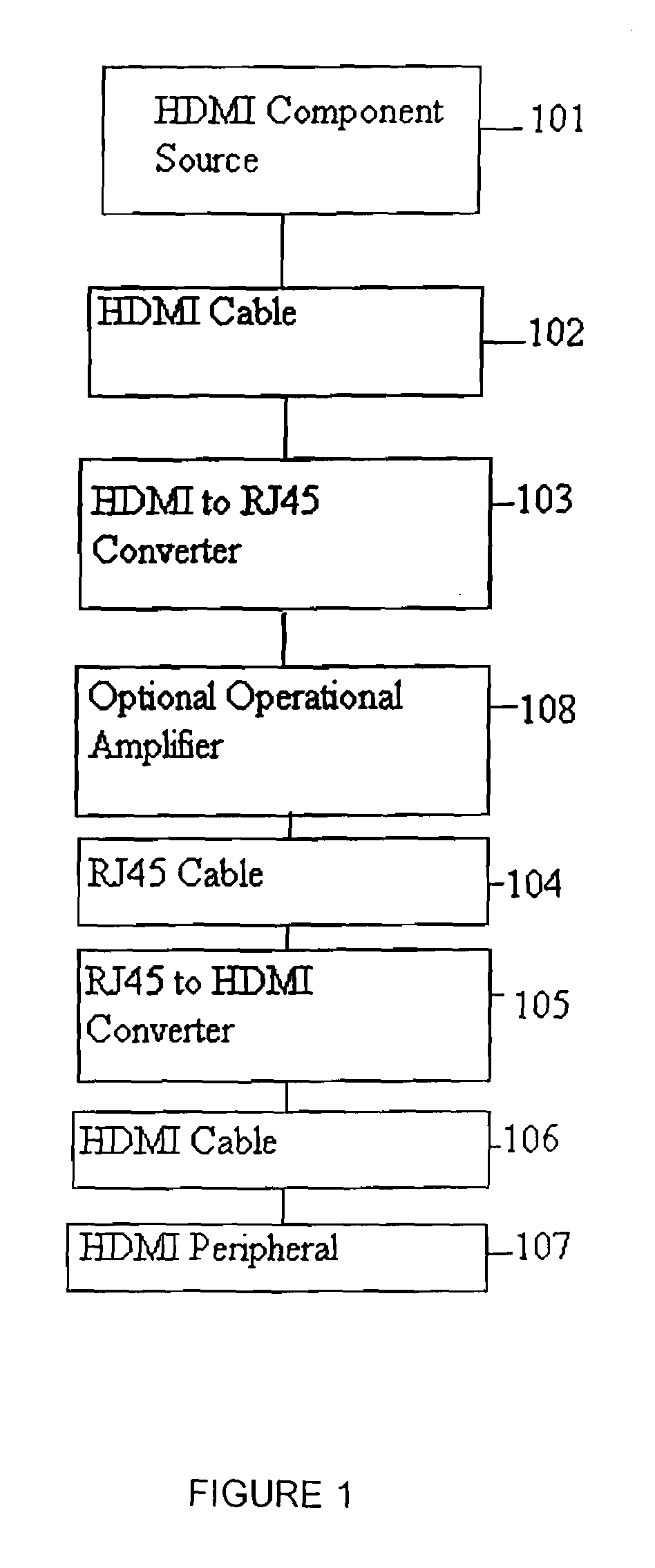
[0014]FIG. 1 is a block diagram of the system of the invention. The component source is the source of the HDMI signal. Component source 101 may be a computer, specifically, the video output of a computer. Component source 101 may also be a DVD player, a television set, or VCR, in short, any thing that is capable of producing a signal under the HDMI standard. Component source 101 typically delivers the signal through a standard DVD jack, although a direct connection to a HDMI cable is also possible. One end of a HDMI cable 102 connects to the output of component source 101. Cable 102 is typically a nineteen (19) wire cable adapted specifically for transmission of HDMI signals. The other end of cable 102 connects to a converter 103. The connection of cable 102 to converter 103 may be done through an HDMI plug and HDMI jack or may be direct. Converter 103 converts the nineteen input signal into a plurality of signals suitable for twisted pair cables. In the preferred embodiment, conver...


PUM


Abstract

A method and apparatus for transmitting a signal to a remote location. The method splits the signal into a multitude of signals that are transmitted down cables. The split signals are collected into a single signal at the receiving end at the remote location. An apparatus for splitting the signals and collecting the split signals is illustrated.

Description

[0001] This application is a continuation in part application of and claims priority to application Ser. No. 11 / 202,950 entitled “HDMI CABLE INTERFACE” filed Aug. 12, 2005, which is a continuation in part application of and claims priority to application Ser. No. 10 / 254,485 entitled “DVI CABLE INTERFACE” filed Sep. 24, 2002.TECHNICAL FIELD [0002] This invention relates to interfaces for electrical devices. In particular, the invention relates to cable for use with digital display devices. With still greater particularity, the invention relates to interconnect boards for connecting a interface to multiple cables. BACKGROUND ART [0003] One interface is the Digital Visual Interface (DVI). One variant of this interface is the High-Definition Multimedia Interface (HDMI). The HDMI is a display interface developed in response to the proliferation of digital flat-panel displays. The HDMI interface is becoming more prevalent and is expected to become widely used for digital display devices, ...

Claims


Application Information

Patent Timeline
IPC IPC(8): H01R13/648
CPCH01R31/005
Inventor GALANG, EINSTEIN C.MARTIN, DEMIAN
Owner MONSTER
Why Eureka
Try Eureka