

Optical element and system using the same
a technology applied in the field of optical elements and systems using the same, can solve the problems of system becoming more sensitive to relative intensity noise, light source instability, and low bit error ra
- Summary
- Abstract
- Description
- Claims
- Application Information
AI Technical Summary
Benefits of technology
Problems solved by technology
Method used
Image

Examples
Embodiment Construction
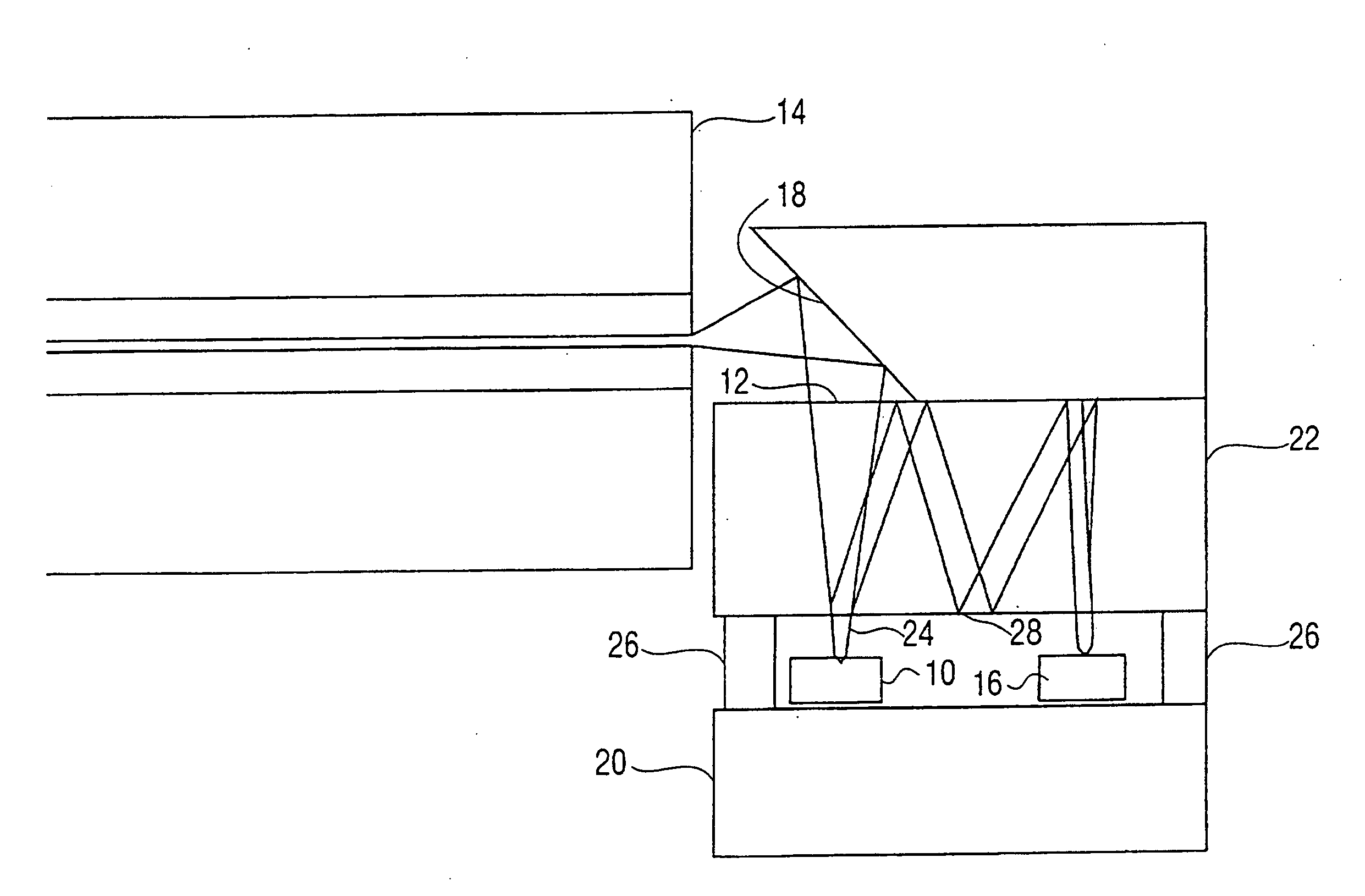
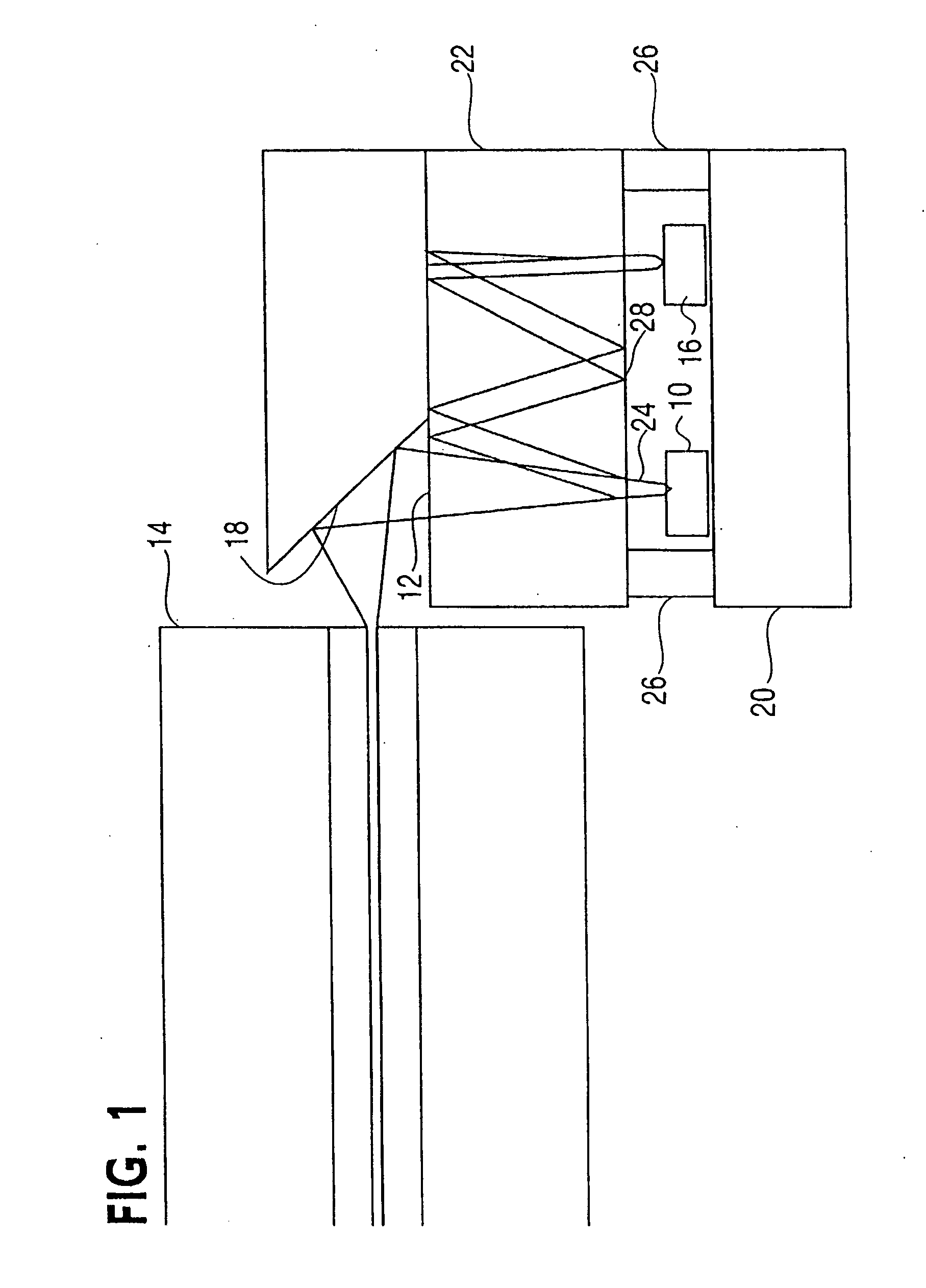
[0019]FIG. 1 illustrates a light source 10, here a VCSEL, a coupler 12 and a multi-mode fiber 14 integrated with a power monitor 16 and a reflective surface 18 for directing the light into the fiber 14. In particular, the light source 10 and the power monitor 16 are provided on a substrate 20. Another substrate 22 has the coupler 12 thereon, preferably on the face furthest from the light source to allow the beam to expand, and a splitting diffractive element 24 which splits off a portion of the light from the light source 10 to be monitored. The substrates 20, 22 are preferably mounted with spacer blocks 26, which provide the desired separation between the substrates 20, 22. The coupler 12 may also be provided in a common housing with the fiber 14.
[0020] The light split off by the diffractive element 24 is directed to the power monitor 16 to monitor the operation of the light source 10. The directed of the light to the power monitor 16 may be achieved by providing appropriately pos...
PUM
 Abstract
Description
Claims
Application Information