Tuned circuit with variable amplitude function and integrated circuit for radio communication device

A technology of tuning circuit and amplitude, applied in the adjustment of resonant circuit, parts of resonant circuit, continuous tuning parts, etc., can solve the problems of exhausted battery and large power consumption.

Inactive Publication Date: 2004-08-04
SANYO ELECTRIC CO LTD
View PDF1 Cites 2 Cited by
  • Summary
  • Abstract
  • Description
  • Claims
  • Application Information

AI Technical Summary

Problems solved by technology

For such a circuit that consumes a lot of power, for example, if a battery-driven remote operating system receiver is used, the battery will be exhausted quickly.

Method used


Image

  • Tuned circuit with variable amplitude function and integrated circuit for radio communication device
  • Tuned circuit with variable amplitude function and integrated circuit for radio communication device
  • Tuned circuit with variable amplitude function and integrated circuit for radio communication device

Examples


Embodiment

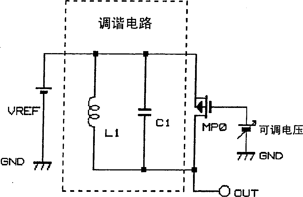
[0034] the said figure 1 An embodiment of the circuit shown is shown in figure 2 circuit diagram. Consists of transistor MP0 figure 1 The resistance value adjustment element R'. In this embodiment, the transistor MP0 is constituted by a p-type channel MOSFET. In addition, a reference voltage Vref (for example, 3V) is applied to one end (left side in the figure) of the coil L1 and the capacitor C1 constituting the parallel resonance circuit of the tuning circuit LC. The AC signal resonant in this LC parallel resonance circuit is output from the coil L1 and the output terminal (the other end) OUT of the capacitor C1.

[0035] Then, by changing the voltage applied to the gate (control electrode) of the transistor MP0, the resistance value R0 of the tuning circuit is changed. There are two methods for changing the voltage applied to the gate of the transistor MP0: a digital driving method in which the transistor MP0 is used as a switching element, and an analog driving met...


PUM


Abstract

A tuning circuit having an amplitude-varying function is disclosed that comprises a coil, a capacitor, and a resistance-adjusting element connected in parallel to the coil and the capacitor for varying resistance at time of resonance of the tuning circuit, wherein the amplitude of an output signal of the tuning circuit is varied by varying the resistance with the resistance-adjusting element.

Description

technical field [0001] The present invention relates to a tuning circuit with a variable amplitude function and an integrated circuit for a wireless communication device. Background technique [0002] exist Figure 9 In , a general example of a tuning circuit for ASK (Amplitude Shift Keying) communication and an AGC (Automatic Gain Control) circuit is shown. The tuning circuit is composed of a coil (inductance) L1 and an LC parallel resonance circuit in which one end of a capacitor (capacity) C1 is connected to a reference voltage Vref. The AGC circuit is composed of a variable gain amplifier (Variable Gain Amp), a rectifier circuit (REC), and a comparator (COMP). The variable gain amplifier adjusts the AC signal from the tuning circuit and outputs it to the output terminal OUT. An amplifier, a detection circuit, a waveform shaping circuit, etc. are connected to this output terminal OUT, and an AC signal whose amplitude has been adjusted is processed (for example, refer to...

Claims


Application Information

Patent Timeline
Patent Type & Authority Applications(China)
IPC IPC(8): H03G3/14G06K19/07H03G3/20H03G3/30H03J1/00H03J3/18H04B1/06H04L27/08
CPCG06K19/0723H03J3/18
Inventor 梅若正博山本洋也关根庆太郎兵库明森尻敬治
Owner SANYO ELECTRIC CO LTD
Why Eureka
Try Eureka