Wireless communication method

a wireless terminal and communication method technology, applied in multiplex communication, transmission monitoring, site diversity, etc., can solve the problems of inability to perform communication at the rate corresponding, inability to accurately predict the reception quality at the time of data signal reception based on the reception quality of the pilot signal, and inability to receive signals in slots. , to achieve the effect of reducing the amount of reverse-link feedback information, avoiding throughput, and small demodulation circuit scal

Active Publication Date: 2007-10-18
HITACHI LTD
View PDF4 Cites 148 Cited by
  • Summary
  • Abstract
  • Description
  • Claims
  • Application Information

AI Technical Summary

Benefits of technology

[0022] In light of the circumstances described above, an object of the present invention is to provide a method in which under application of an inter-base-station cooperative system, to avoid the reduction of the throughput as a result of avoidance of the interference and, also in the slot in which the interference occurs, to enable communication at a suitable forward-link transmission rate. Besides, an object of the present invention is to provide a wireless communication method in which under the application of the inter-base-station cooperative system, the amount of reverse-link feedback information is decreased, and the scale of the demodulation circuit of the wireless terminal can be made small.
[0045] According to the invention, under application of an inter-base-station cooperative system, as a result of avoidance of the interference, the reduction of the throughput is avoided, and also in the slot in which the interference occurs, communication at a suitable forward-link transmission rate is enabled. Besides, a wireless communication method and a wireless communication system can be provided in which under the application of the inter-base-station cooperative system, the amount of reverse-link feedback information is decreased, and the scale of the demodulation circuit of the wireless terminal can be made small.
[0046] According to the invention, even if a variation in the interference state of each slot occurs, the communication can be performed while using the suitable data rate. Thus, the reduction of the throughput due to this can be prevented.

Problems solved by technology

However, the forward-link data rate requested by the wireless terminal is one value estimated from the common pilot signal and is a value independent of the presence / absence of the interference, in the case where the interference from the adjacent cell occurs, there occurs a possibility that the signal of the slot can not be received.
In the related art, with respect to a slot in which interference occurs, it is difficult to accurately predict the reception quality at the time when the data signal is received based on the reception quality of the pilot signal.
However, since the forward-link communication rate requested from the terminal is a single value independent of the presence / absence of the interference, there is a case where the communication can not be performed at the rate corresponding to the change in the reception quality of each slot.
Thus, a suitable throughput can not be obtained.
However, in this system, following problems occur according to the distribution of the wireless terminals.

Method used


Image

  • Wireless communication method
  • Wireless communication method
  • Wireless communication method

Examples


Embodiment Construction

[0053] Hereinafter, an embodiment will be described, however, the invention is not limited to this.

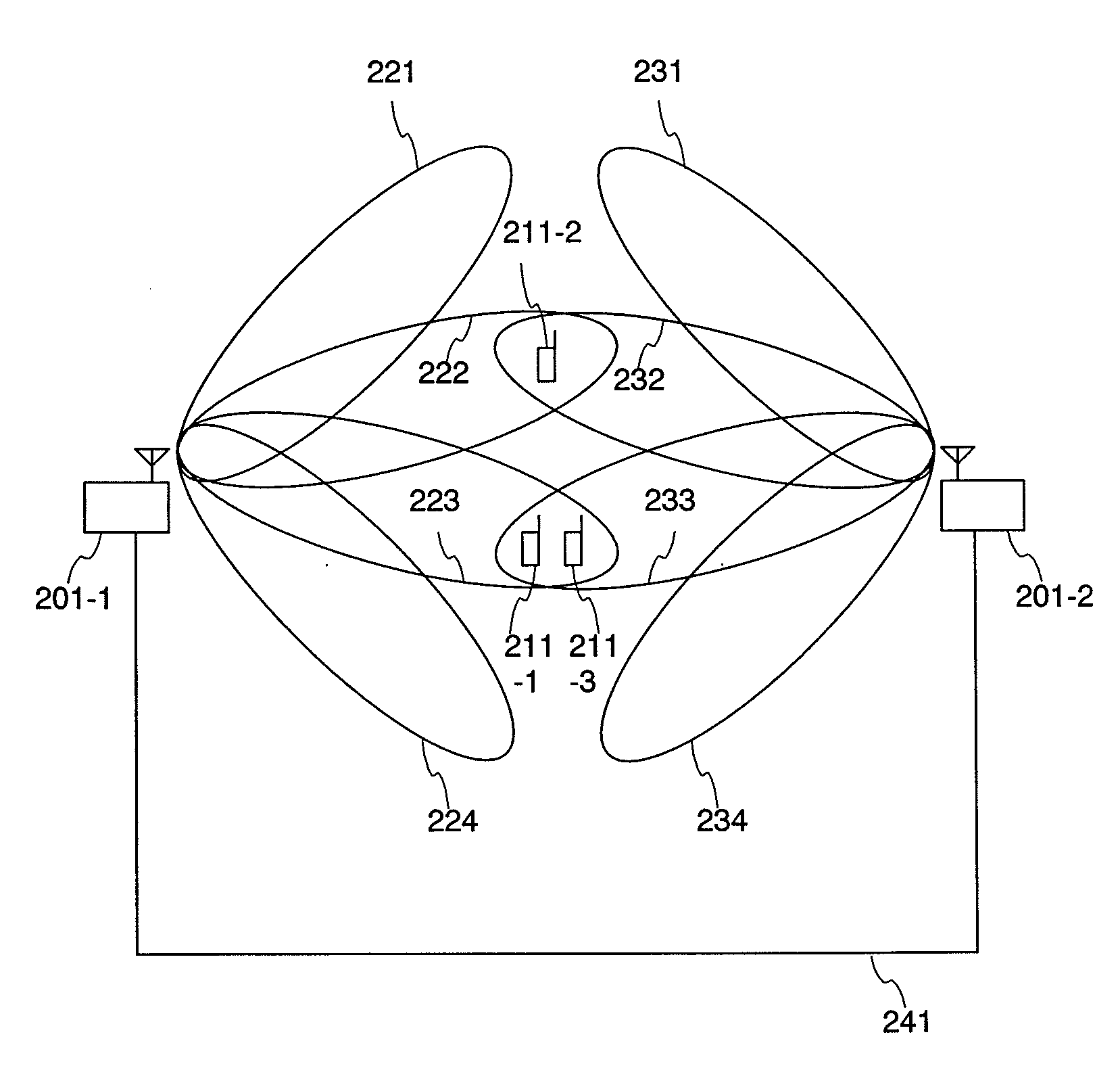
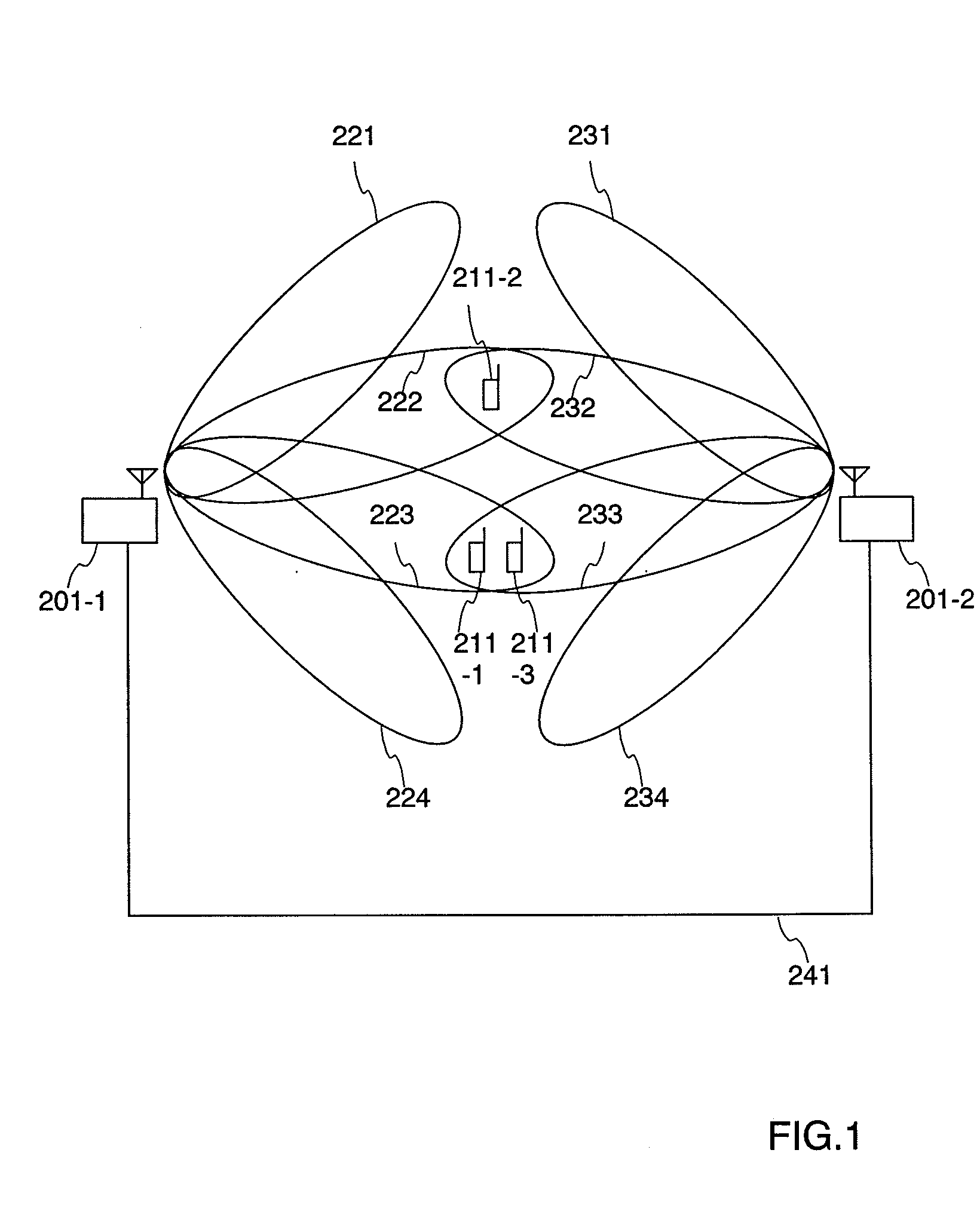
[0054]FIG. 1 is a structural view of a wireless communication system of the embodiment.

[0055] The wireless communication system includes, for example, two base stations (201-1, 201-2) and a plurality of wireless terminals (211-1, 211-2, 211-3). Incidentally, although the illustrated example includes the two base stations and the three wireless terminals, more (or less) plural ones may be provided respectively. In the case where there are three or more base stations, for example, the structure may be considered such that every two of the plurality of base stations are paired.

[0056] In FIG. 1, for example, it is assumed that the wireless terminals 211-1 and 211-2 are connected to the first base station 201-1 (hereinafter denoted by AP1), and the wireless terminal 211-3 is connected to the second base station 201-2 (hereinafter denoted by AP2). In these, for example, each wireless term...


PUM


Abstract

A terminal 211 measures pilot signals transmitted in directional (beam) patterns from an adjacent cell and an own cell, and estimates reception qualities with the presence (high) / absence (low) of the interference from the adjacent cell. The terminal 211 requests data rate request values (DRC1, DRC2) corresponding to the reception qualities with the presence / absence of the interference to the base station 201. The base station 201 shares beam direction schedule with an adjacent cell base station, and confirms the presence / absence of interference to the terminal 211 for each slot. In accordance with the presence / absence of the interference, the base station 201 selects a suitable one of the two values of the data rates requested from the terminal 211, and modulates the data and transmits it.

Description

CROSS-REFERENCE TO RELATED APPLICATION [0001] This application relates to U.S. patent application Ser. No. 11 / 508,200 filed on Aug. 23, 2006, based on Japanese Patent Application Number 2006-046238 filed on Feb. 23, 2006, which is assigned to the present assignee. The content of the application is incorporated herein by reference.BACKGROUND OF THE INVENTION [0002] The present invention relates to a wireless communication method, and particularly to a wireless communication method in which in a wireless system to perform cellular communication, an array antenna type wireless apparatus including a plurality of antennas is used, beams are formed in time division and packet transmission is performed. [0003] Antennas used in cellular system base stations are directional antennas to form sectors, and in some antennas, an array antenna to further subdivide the sector is not added. The respective base stations use the same frequency channel and the mutual communication causes interference. ...

Claims


Application Information

Patent Timeline
Patent Type & Authority Applications(United States)
IPC IPC(8): H04Q7/20H04B1/7103H04J13/00H04W16/02H04W16/24H04W16/28H04W72/04H04W92/20
CPCH04B7/024H04W16/28H04W16/24
Inventor TAIRA, MASANORIFUJISHIMA, KENZABUROUWANO, KOKI
Owner HITACHI LTD
Why Eureka
Try Eureka