Connector

a technology of connectors and connectors, applied in the direction of couplings/cases, coupling device connections, coupling parts engagement/disengagement, etc., can solve the problems of inability to maintain watertight characteristics between male and female connectors, and difficulty in maintaining conventional lever-type connectors

Active Publication Date: 2007-12-20
YAZAKI CORP
View PDF6 Cites 4 Cited by
  • Summary
  • Abstract
  • Description
  • Claims
  • Application Information

AI Technical Summary

Benefits of technology

[0021]With the construction described above, since the pressing projection is arranged in the proximity of the end part of the female connector, said end part being situated in the proximity of the male connector, therefore the pressing projection can securely allow the end part of the female connector to adhere to the male connector, even if said end part tends to extend, in particular, after the male connector and the female connector fit to each other.
[0022]With the construction described above, since the pressing projection is arranged in the proximity of the end part of the female connector, said end part being situated in the proximity of the male connector, therefore the pressing projection can securely allow the end part of the female connector to adhere to the male connector, even if said end part tends to extend, in particular, after the male connector and the female connector fit to each other. Therefore, the male and female connectors after the fitting can be securely maintained watertight to each other.

Problems solved by technology

Therefore, it has been difficult for the conventional lever-type connector to maintain a watertight characteristic between the male and female connectors.
However, in such a case, operation force required to rotate the lever upon fitting of the male and female connectors becomes stronger, causing the fitting of the connectors to be difficult or resulting in that the packing is turned up by the housing of the female connector and therefore, the packing is unable to maintain watertight characteristic between the male and female connectors.

Method used


Image

  • Connector
  • Connector
  • Connector

Examples


Embodiment Construction

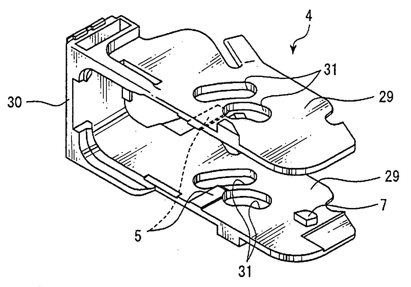
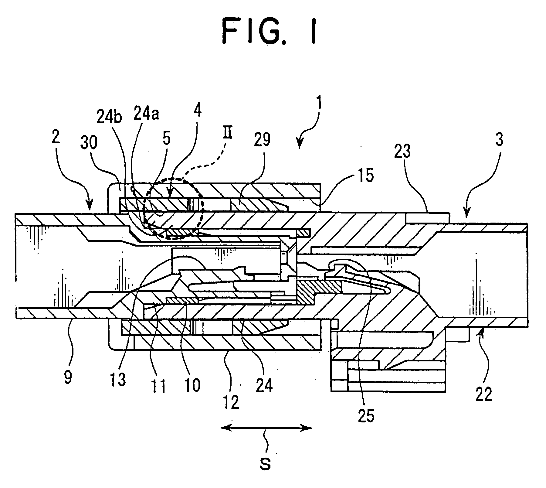
[0029]In the following, a connector according to a preferred embodiment of the present invention will be explained with reference to FIGS. 1-6. As shown in FIG. 1, a connector 1 according to a preferred embodiment of the present invention includes a male connector 2, female connector 3, lever 4 and a pair of pressing projections 5.

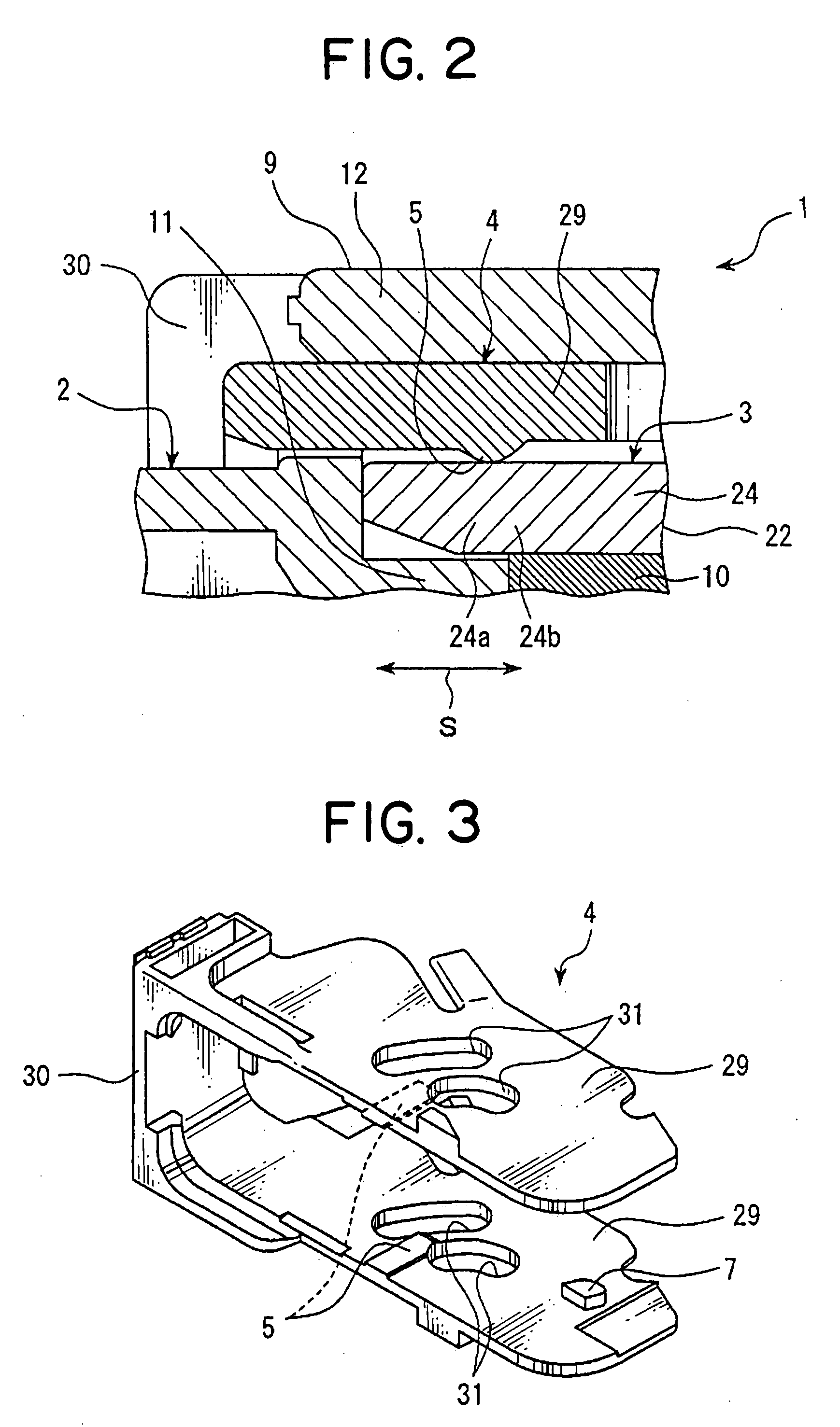
[0030]The male connector 2 includes a connector housing 9, female terminal fitting (hereinafter, female terminal; not shown in the figure), and packing 10. As shown in FIG. 1, the connector housing 9 includes integrally a box-shaped inner housing 11 and a tube-shaped outer cover 12. The inner housing 11 is provided with a terminal receiving chamber 13 and formed in a box-shape. Each terminal receiving chamber 13 of the inner housing 11 receives the female terminal.

[0031]The outer cover 12 is formed integrally with the inner housing 11 on a condition that the outer cover 12 receives the inner housing 11 inside. An inner surface of the outer cover 12 is situ...


PUM


Abstract

The connector includes: a male connector; a female connector which fits to the male connector when the male connector enters inside the female connector; a lever which is rotatably attached to one of the male connector and the female connector, and rotates so as to allow the male connector and the female connector to approach or leave each other; and a pressing projection which projects from one of the lever and the female connector toward the other of the lever and the female connector, 1o wherein when the male connector and the female connector fit to each other, the pressing projection presses the female connector in a direction in which the male connector and the female connector adhere to each other. The male and female connectors can be easily securely fit to each other, and the male and female connectors after fitting can be maintained watertight to each other.

Description

BACKGROUND OF THE INVENTION[0001](1) Field of the Invention[0002]The present invention relates to a connector including: a male connector and a female connector which are fit to each other; and a lever rotatably provided to one of the male connector and the female connector.[0003](2) Description of the Related Art[0004]So far, various types of lever-type connector have been utilized for fitting easily a male connector and a female connector to each other (for example, see Japanese Patent Application Laid-Open No. H11-102747).[0005]A so-called lever-type connector includes: a male connector; a female connector which receives the male connector therein so as to fit to the male connector; and a lever rotatably attached to the male connector. The male connector is formed in a box-shape and attaches a packing for maintaining a watertight characteristic between the male connector and the female connector.[0006]The female connector is formed in a box-shape. The lever rotates relative to th...

Claims


Application Information

Patent Timeline
Patent Type & Authority Applications(United States)
IPC IPC(8): H01R13/62
CPCH01R13/5219H01R13/6295H01R13/62938H01R13/52H01R13/62933
Inventor TAKAHASHI, TOSHIHARU
Owner YAZAKI CORP
Why Eureka
Try Eureka