Image forming apparatus

a technology of image forming and forming apparatus, which is applied in the direction of electrographic process apparatus, instruments, optics, etc., can solve the problems of lowering the productivity of image forming, unable to perform correct control of densities, and the sensitivity characteristics of density sensors cannot be kept almost the same, so as to achieve the effect of not lowering the productivity

Inactive Publication Date: 2008-01-10
CANON KK
View PDF7 Cites 6 Cited by
  • Summary
  • Abstract
  • Description
  • Claims
  • Application Information

AI Technical Summary

Benefits of technology

[0007]The present invention provides an image forming apparatus that can provide a quality image in a stable manner without lowering the productivity.
[0015]According to the present invention, a quality image can be provided in a stable manner without the productivity lowered.

Problems solved by technology

That lowers the productivity of image forming.
However, as the sensitivity characteristics of the density sensors may vary according to the temperature, the water content and the like, or may vary according to changes with time and in durability, the sensitivity characteristics of density sensors cannot be kept almost the same.
Accordingly, it is impossible to perform correct control over the densities.
That makes it difficult to supply a quality image in a stable manner.

Method used


Image

  • Image forming apparatus
  • Image forming apparatus
  • Image forming apparatus

Examples


first embodiment

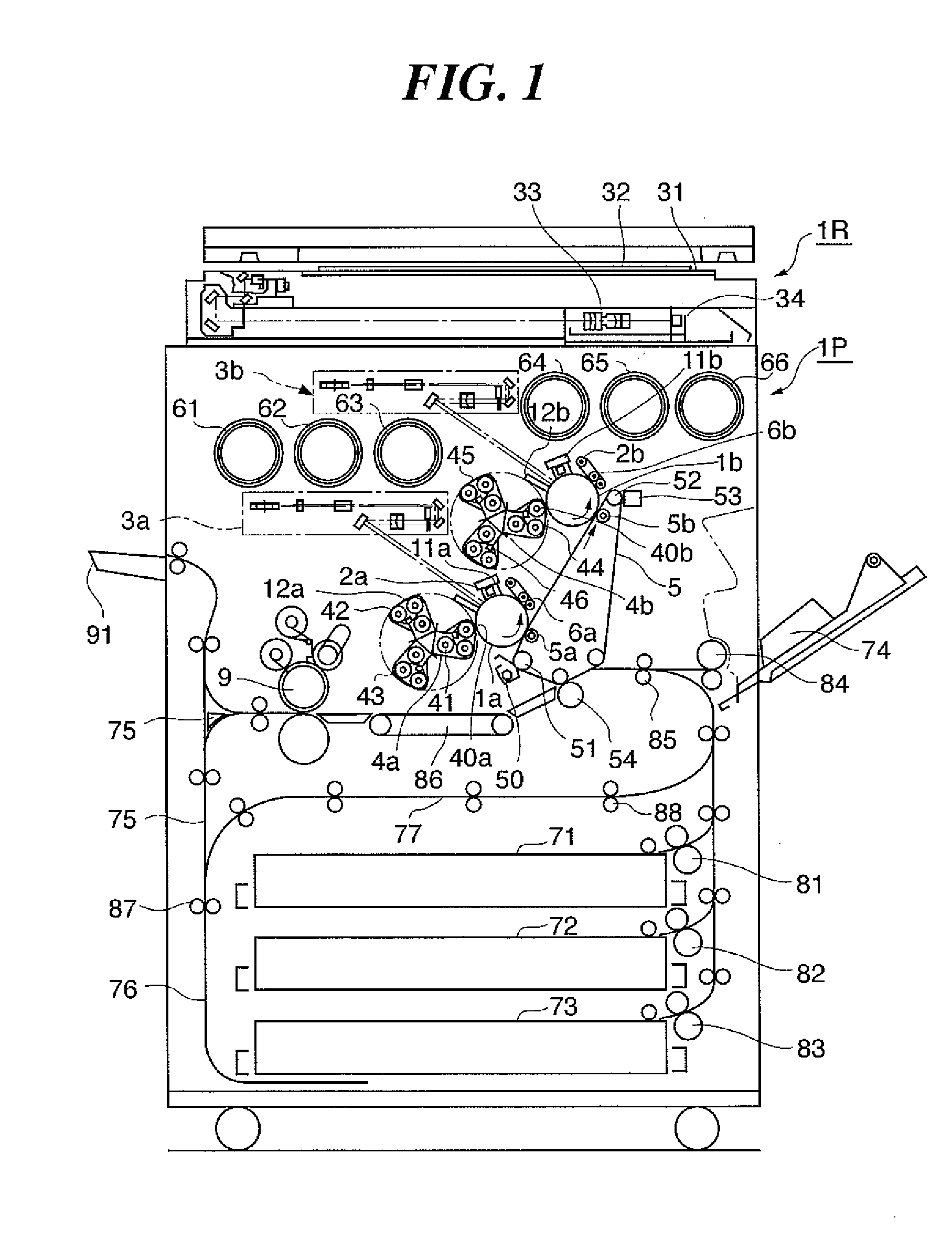
[0027]FIG. 1 is a vertical cross-sectional view showing a configuration of an image forming apparatus according to the present invention. In the embodiment, a full-color image forming apparatus will be described.

[0028]As shown in FIG. 1, the full-color image forming apparatus has a reader unit 1R that can read a color image and a printer unit 1P that can output a print of a color image.

[0029]The reader unit 1R performs exposure scanning on a manuscript 30 placed on a sheet of manuscript table glass 31 by using an exposure lamp 32, and forms an image of a reflected light from the manuscript 30 on a full-color CCD sensor (hereinafter referred to as “the CCD”) 34 by using a lens 33. The CCD 34 converts the formed light figure into R, G, B signals and output them. The output R, G, B signals are subjected to predetermined image processing in an image processing unit and then sent out to the printer unit 1P via an image memory (not shown).

[0030]Into the printer unit 1P, an image signal fr...

second embodiment

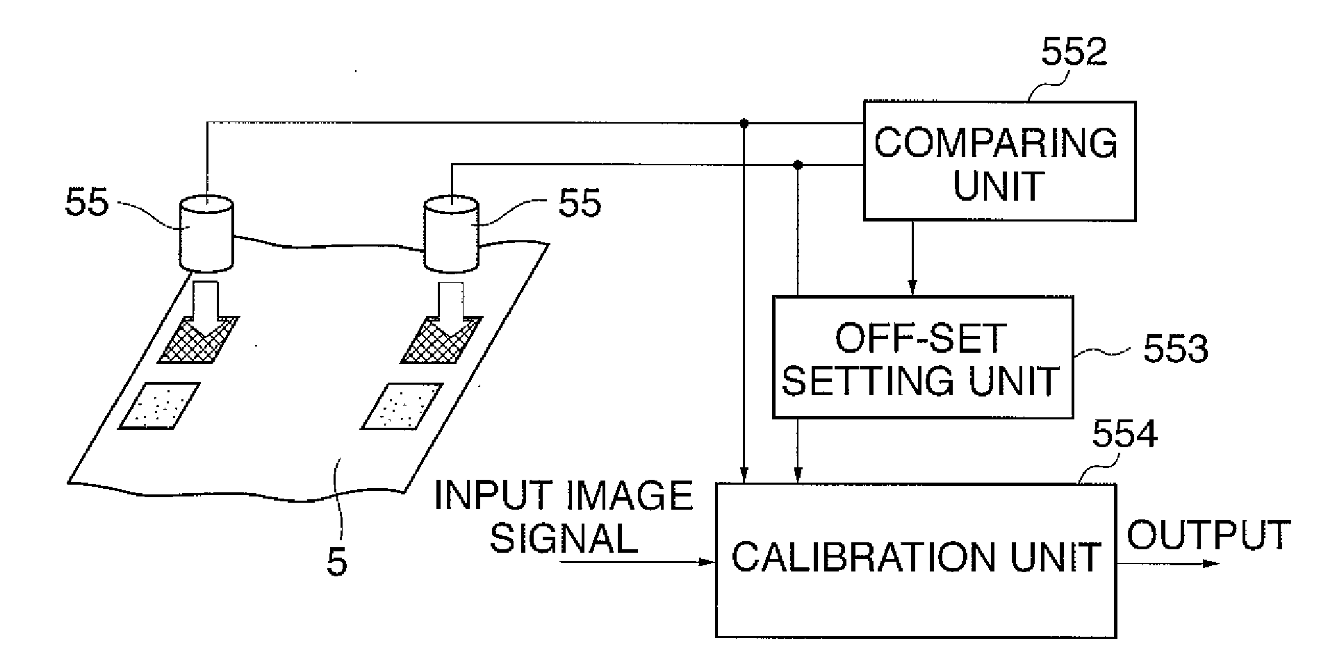
[0093]Now, the present invention will be described with reference to FIG. 9. FIG. 9 is a flowchart showing the procedure of output correction-controlling processing for correcting outputs from the respective density sensing sensor 55 in an image forming apparatus according to a second embodiment of the present invention.

[0094]In the first embodiment, if a difference between the output value of the one of the density sensing sensors 55 and the output value of the other of the density sensing sensors 55 exceeds a predetermined value, it can be considered that any one of the density sensing sensors 55 has broken down. As a reason for the difference exceeding the predetermined value other than the above-mentioned one, the toribo amount of the toner in the developing device is uneven at the forefront and the back of the developing device. That is, there is a difference between the toribo amount of the toner for developing the test patch corresponding to one of the density sensing sensors...


PUM


Abstract

An image forming apparatus that can provide a quality image in a stable manner without lowering the productivity. A reference image forming unit forms reference images on a transfer member. A plurality of sensing units detect densities of the formed reference images. A control unit adjusts respective output values from the plurality of sensing units according to a difference between the output values from the plurality of sensing units. The control unit performs error processing according to the difference between the output values from the plurality of sensing units when the control unit adjusts the output values from the plurality of sensing units.

Description

BACKGROUND OF THE INVENTION[0001]1. Field of the Invention[0002]The present invention relates to an image forming apparatus, and more particularly, to an image forming apparatus that has a plurality of density sensing units arranged in the main scanning direction so as to be able to read a plurality of test patches for correcting density sensing output that are arranged in the main scanning direction at the same time.[0003]2. Description of the Related Art[0004]A configuration for forming a test patch (reference image) for adjustment of the apparatus, reading the test patch and correcting an image based on the read result (color registration control, density control (Dmax control, Dhalf control)) has been proposed for an image forming apparatus. With the configuration, however, the test patch is formed and read, with the usual image forming operation retarded or suspended, when the image forming apparatus is powered on, when the process devices are exchanged, or when a predetermined...

Claims


Application Information

Patent Timeline
Patent Type & Authority Applications(United States)
IPC IPC(8): G03G15/00
CPCG03G2215/00059G03G15/5058G03G15/0173
Inventor SAIDA, TADAAKIMORI, AKIHITOSEKIGUCHI, NOBUOTAKAHASHI, KEITA
Owner CANON KK
Why Eureka
Try Eureka