Sheet folding processing apparatus and image forming system including the same

Active Publication Date: 2020-10-15
COPYER
View PDF0 Cites 1 Cited by
  • Summary
  • Abstract
  • Description
  • Claims
  • Application Information

AI Technical Summary

Benefits of technology

[0011]According to the present invention, it is possible to adjust a position of a rear end of a sheet, that is, an upstream end in the conveyance direction when additional folding processing is performed on a fold line of the sheet by appropriately setting a predetermined conveyance amount by which the fold line of the sheet passes through the additional folding position until a folding roller pair is temporarily stopped and reversely rotated. Thus, it is possible

Problems solved by technology

In the sheet folding apparatus disclosed in Japanese Patent Application Laid-Open No. 2012-171727, the re-pressurizing roller is moved from one end to another end of the sheet along the fold line of the sheet at the time of the additional folding processing, and

Method used


Image

  • Sheet folding processing apparatus and image forming system including the same
  • Sheet folding processing apparatus and image forming system including the same
  • Sheet folding processing apparatus and image forming system including the same

Examples


second embodiment

[0093]FIGS. 10 to 12 illustrate the folding processing and the additional folding processing performed by the sheet folding processing apparatus B. The above processing may be performed according to the procedure shown in the flowchart of FIG. 13, for example.

[0094]Here, since the folding processing of FIGS. 10A to 10C and FIGS. 11D to 11F is the same as the folding processing of FIGS. 6A to 6C and FIGS. 7D to 7F in the first embodiment, description thereof will be omitted. Similarly, since processing of steps St51 to St55 of FIG. 13 is also the same as processing of steps St71 to St75 of FIG. 9 in the first embodiment, description thereof will be omitted.

[0095]After the first fold line 132 is formed at step St55 as illustrated in FIG. 11F, when the first fold line 132 reaches the additional folding processing position (step St56) as illustrated in FIG. 12G, the folding roller pair 105 is stopped (step St57), and the first fold line 132 is positioned at the additional folding proces...

first embodiment

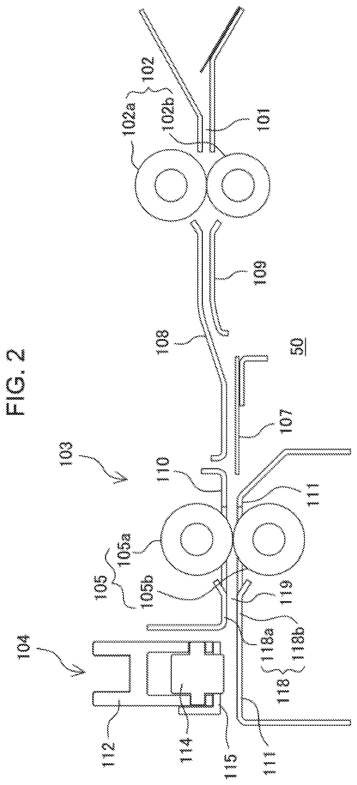
[0097]Similarly to step St82, when the conveyance of the sheet S to the downstream side is started, each activation of the conveyance roller pair 102 and the folding roller pair 105 may be started with a time difference. Specifically, for example, the folding roller pair 105 is activated first, and then the conveyance roller pair 102 is activated after a predetermined time has elapsed. Due to setting an appropriate time difference between the activation start of the conveyance roller pair 102 and that of the folding roller pair 105, the second loop FL2 formed in the loop forming space 50 can be eliminated or reduced. The second loop FL2 may be formed after the loop FL is drawn into the folding roller pair 105. Here, since the additional folding processing of the second fold line 133 illustrated in FIG. 12I is the same as the additional folding processing of FIG. 8I of the first embodiment, description thereof will be omitted.

[0098]In the additional folding mechanism of the present e...


PUM

PropertyMeasurementUnit
Timeaaaaaaaaaa

Abstract

A sheet folding processing apparatus performs folding processing on continuously conveyed sheets without lowering productivity. A sheet folding processing apparatus includes a conveyance roller pair, a folding roller pair forming a plurality of fold lines by bending a sheet conveyed from the conveyance roller pair in Z-shape, an additional folding roller and a lower folding guide arranged downstream of the folding roller pair to face each other and pressing the fold line of the sheet in corporation with each other, and a controller controlling operation of the above. The controller controls the folding roller pair to convey the sheet with the fold line downstream in a conveyance direction until the fold line passes through the additional folding position by a predetermined conveyance amount, to return the sheet upstream by reversely rotating the folding roller pair, and to position the fold line to the additional folding position for additional folding processing.

Description

CROSS-REFERENCE TO RELATED APPLICATION[0001]The present application is based on and claims priority of Japanese Patent Application No. 2019-075417 filed on Apr. 11, 2019, the disclosure of which is incorporated herein.TECHNICAL FIELD[0002]The present invention relates to a sheet folding processing apparatus which performs folding processing on a sheet, and an image forming system including the sheet folding processing apparatus such as a copier, a printer, a facsimile, and a compound machine of the above.BACKGROUND ART[0003]Conventionally, a sheet folding processing apparatus (post processing apparatus) which is installed in an image forming system such as a copier and a printer and performs folding processing on an image formed sheet has been widely known. The folding processing includes double folding in which a sheet is folded at a center position, triple folding in which a sheet is folded inward at two positions, and so-called Z folding in which a sheet is alternately folded inw...

Claims


Application Information

Patent Timeline
IPC IPC(8): B65H45/14B65H45/04B65H45/20
CPCB65H45/20B65H45/14B65H45/04B65H2801/06B65H2701/13212B65H2301/51232B65H45/18B65H2801/27G03G15/6582G03G2215/00877G03G15/6517
Inventor ATSUMI, KEIICHISAKANO, AKIHITO
Owner COPYER
Why Eureka
Try Eureka