Resecting device

Inactive Publication Date: 2008-01-10
YATES LEROY L
View PDF27 Cites 33 Cited by
  • Summary
  • Abstract
  • Description
  • Claims
  • Application Information

AI Technical Summary

Benefits of technology

[0011]The present invention consists of an electrosurgical resecting device that is new and different from the prior art. The present resecting device differs from the prior art in that it has both straight jaw and angled jaw embodiments wherein the distance between the jaw members is constant along the length of the jaws. The angular jaw embodiments may be engineered to accommodate a specific pelvic vascular structure corresponding to a specific surgical procedure, and to allow for precise placement of the device inside the abdominal cavity. The present device also differs from the prior art because it provides

Problems solved by technology

Numerous patents exist for surgical devices designed for endoscopic cholecystectomy; however, there are currently no dedicated devices for endoscopic pelvic surgery.
The endoscopic cholecystectomy devices now in use a

Method used


Image

  • Resecting device
  • Resecting device
  • Resecting device

Examples


first embodiment

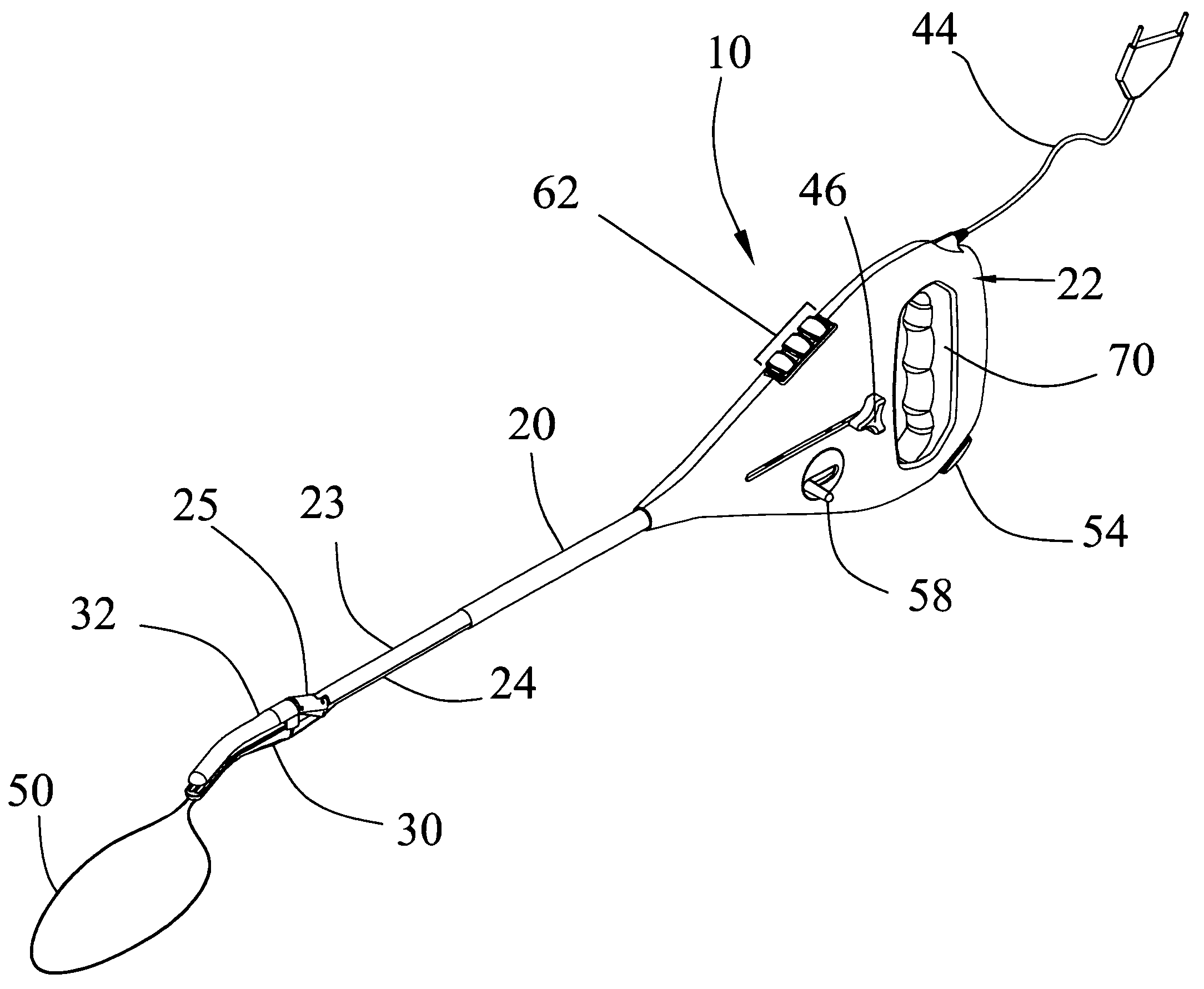
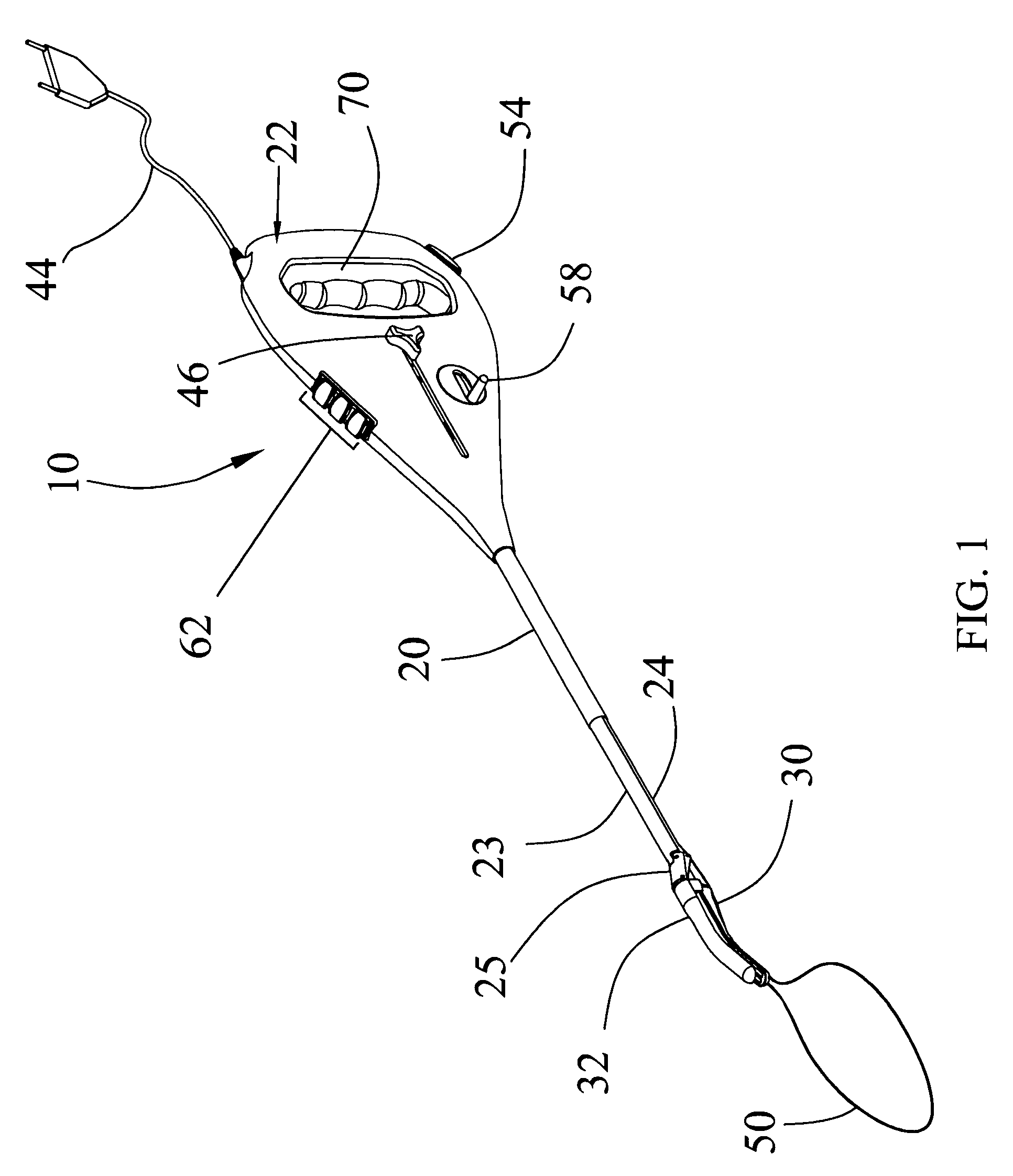
[0013]FIG. 1 is a perspective view of the present invention.

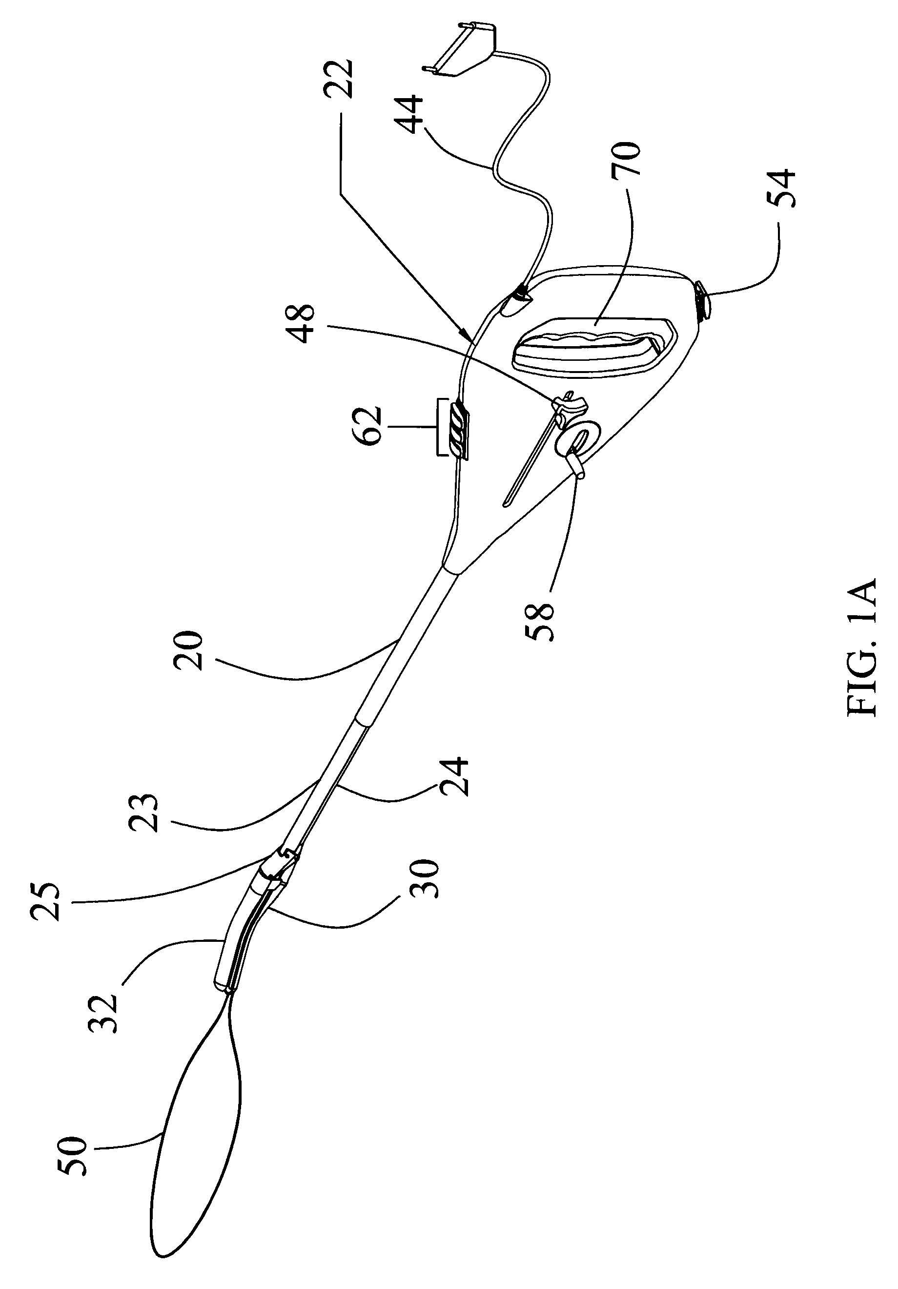
[0014]FIG. 1A is another perspective view of the first embodiment of the present invention.

[0015]FIG. 2 is a detailed view of the internal portions of the handle of the first embodiment.

[0016]FIG. 2A is a detailed, cutaway view of the handle of the first embodiment.

[0017]FIG. 3 is a detailed view of the first embodiment of the jaw members.

[0018]FIG. 3A is another detailed view of the first embodiment of the jaw members.

[0019]FIG. 3B is a cross-sectional view of the link and the jaw members in the first embodiment of the jaw members.

second embodiment

[0020]FIG. 4 is a detailed view of the jaw members in an open position.

[0021]FIG. 4A is a detailed view of the second embodiment of the jaw members in a closed position.

third embodiment

[0022]FIG. 5 is a detailed view of the jaw members in an open position.

[0023]FIG. 5A is a detailed view of the third embodiment of the jaw members in a closed position.


PUM


Abstract

A resecting device is disclosed. The resecting device comprises: a handle having a jaw trigger slidably engaged with said handle and mechanically engaged with a spring mechanism communicating a biasing force to said jaw trigger; a fixed shaft portion having a first and a second end, wherein said fixed shaft portion first end is affixed to said housing, wherein said fixed shaft portion second end forms a first jaw member, and wherein said first jaw member has a tissue contact area; and a slidable shaft portion in communication with said spring mechanism and slidable relative to said fixed shaft portion.

Description

CROSS REFERENCE TO RELATED APPLICATIONS[0001]Applicant claims priority under 35 U.S.C. §119 (e) of provisional U.S. patent application Ser. No. 60,818,847 filed on Jul. 6, 2006, which is incorporated by reference herein.FIELD OF INVENTION[0002]This invention relates to a surgical instrument and, more specifically, to a multi-polar electrosurgical resecting device.STATEMENT REGARDING FEDERALLY SPONSORED RESEARCH OR DEVELOPMENT[0003]No federal funds were used to develop or create the invention disclosed and described in the patent application.REFERENCE TO SEQUENCE LISTING, A TABLE, OR A COMPUTER PROGRAM LISTING COMPACT DISK APPENDIX[0004]Not ApplicableAUTHORIZATION PURSUANT TO 37 C.F.R. §§1.171 (d), (c)[0005]A portion of the disclosure of this patent document contains material that is subject to copyright and trademark protection. The copyright owner has no objection to the facsimile reproduction by anyone of the patent document or the patent disclosure, as it appears in the Patent an...

Claims


Application Information

Patent Timeline
IPC IPC(8): A61B18/14
CPCA61B18/14A61B18/1445A61B18/1485A61B2017/2945A61B2018/00916A61B2018/1407A61B2018/1412A61B2018/1432A61B2018/1455A61B18/1447
Inventor YATES, LEROY L.
Owner YATES LEROY L
Why Eureka
Try Eureka