Quick-detachable mounting assembly

Active Publication Date: 2008-03-13
JARLLYTEC CO LTD
View PDF7 Cites 7 Cited by
  • Summary
  • Abstract
  • Description
  • Claims
  • Application Information

AI Technical Summary

Benefits of technology

[0008]The present invention has been accomplished under the circumstances in view. According to one aspect of the present invention, the quick-detachable mounting assembly comprises a mounting unit and a locking unit. The mounting unit comprises a mounting plate for supporting an external member, and a coupling plate coupled to the mounting plate. The mounting plate has a plurality of mounting through holes on diagonal corners thereof for fastening to an external member to be supported thereon. The coupling plate has at least one hook protruded from a top side thereof, a stop flange downwardly extending from a bottom side thereof, and at least one opening at one of two opposite sides of the stop flange. The locking unit comprises a connecting plate, which has at least one hook hole disposed near a top side thereof and respectively coupled to the at least one hook of the coupling plate of the mounting unit, a flat bottom lug downwardly extending from a bottom side thereof; and a pivot hole near a to

Problems solved by technology

Nowadays, flat-panel display devices are made greater than ever, resulting in a heavy weight.
Because the big-size flat-panel display device is the main body when compared to the bracket or suspension arm, it is not a good way to accommodate the big-size flat-panel display device to the parts of the bracket or suspension arm when mounting the big-size

Method used


Image

  • Quick-detachable mounting assembly
  • Quick-detachable mounting assembly
  • Quick-detachable mounting assembly

Examples


Embodiment Construction

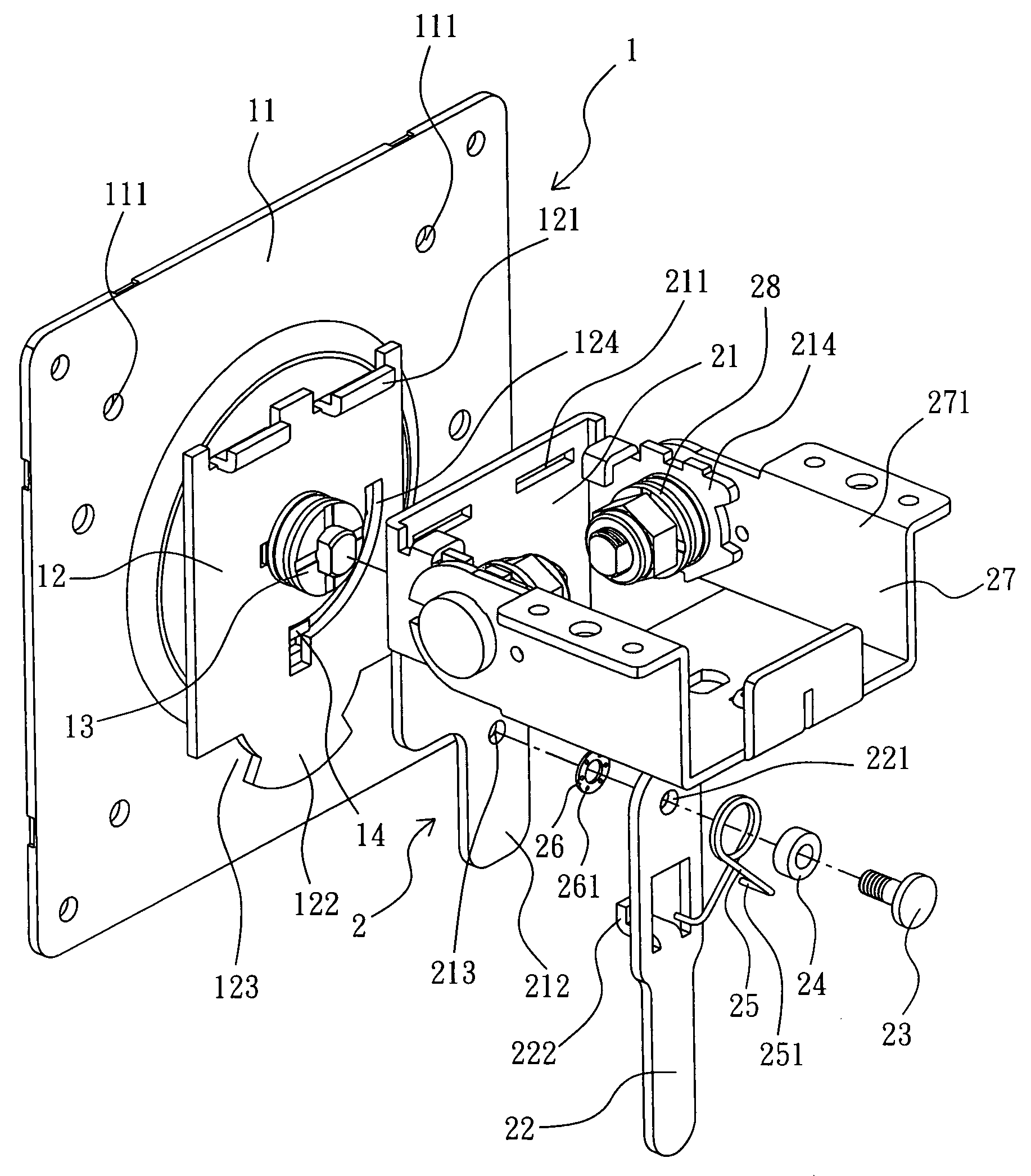
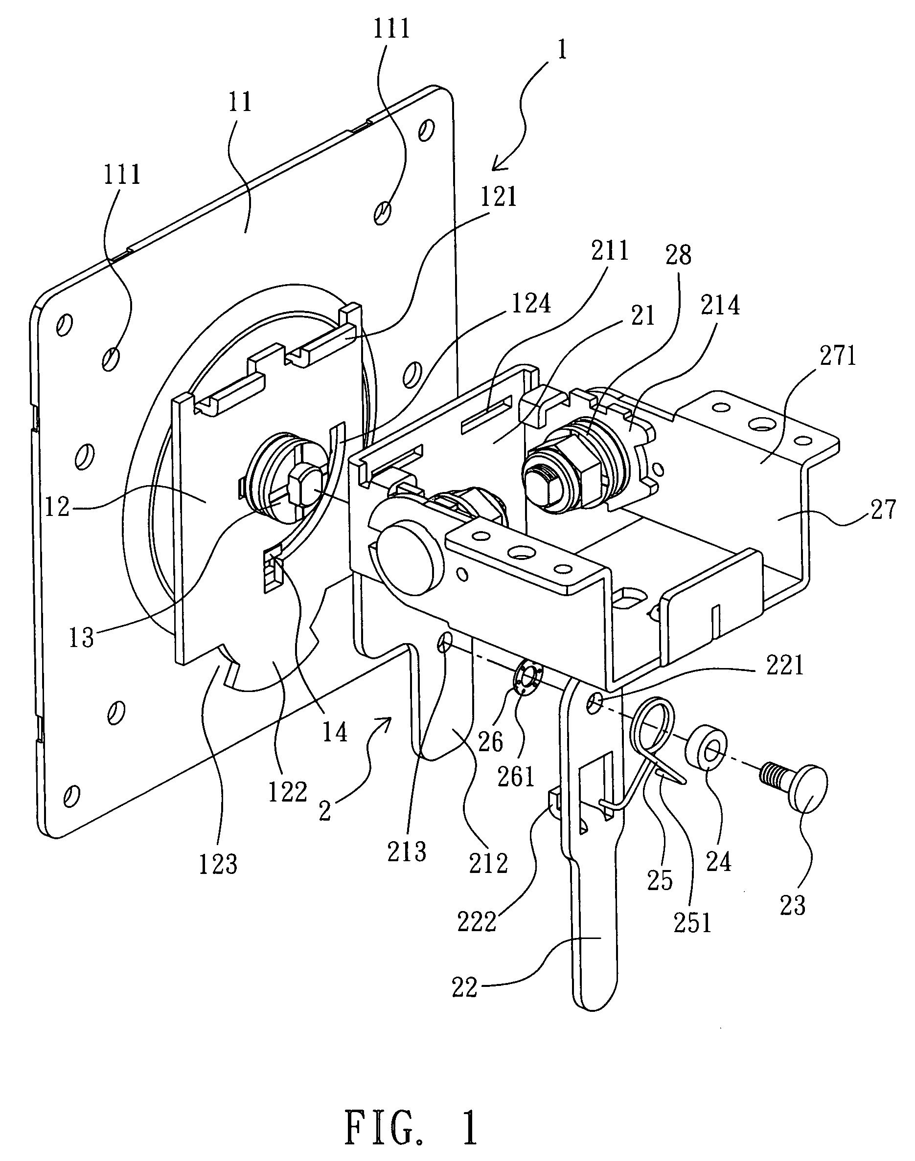
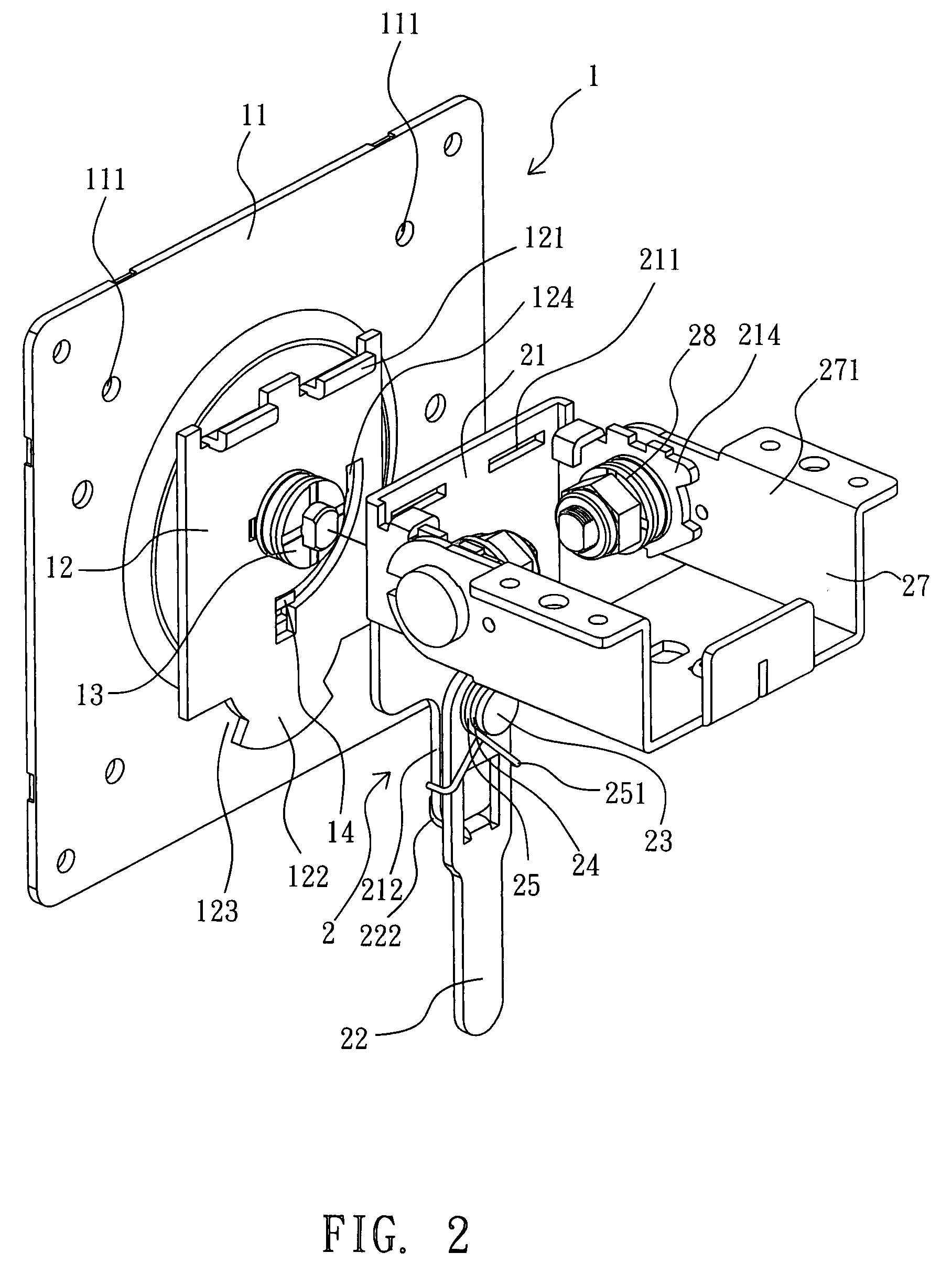
[0017]Referring to FIG. 1, a quick-detachable mounting assembly in accordance with the present invention is shown comprised of a mounting unit 1 and a locking unit 2.

[0018]The mounting unit 1 comprises a mounting plate 11 and a coupling plate 12. The mounting plate 11 is a rectangular plate having a plurality of mounting through holes 111 cut through the front and back sides at locations corresponding to the oblique lines that extend from the center to the four comers of the mounting plate for the mounting of fastening members such as screws to affix the mounting plate 11 to the back side of the load, for example, flat-panel display (not shown). The coupling plate 12 is pivotally connected to the center of the back side of the mounting plate 11 with a pivot 13, having two hooks 121 bilaterally disposed at the top side, a sector-like stop flange 122 downwardly extending from the bottom side, and two openings 123 at two sides of the sector-like stop flange 122. The hooks 121 are forme...


PUM


Abstract

A quick-detachable mounting assembly is disclosed to include a mounting unit formed of a mounting plate for supporting an external member and a coupling plate coupled to the mounting plate, the coupling plate having L-shaped top hooks and a bottom stop flange, and a locking unit formed of a coupling plate hung on the top hooks of the connecting plate and a spring-supported locking bar pivoted to the connecting plate and biasable relative to the connecting plate between the locking position where a backward locking tongue of the locking bar is hooked on a bottom stop flange of the coupling plate and a flat bottom lug of the connecting plate to lock the connecting plate to the coupling plate and the unlocking position where the locking tongue is suspending in one opening at one side of the bottom stop to release the connecting plate from the coupling plate for allowing removal of the connecting plate from the coupling plate.

Description

BACKGROUND OF THE INVENTION[0001]1. Field of the Invention[0002]The present invention relates generally to a mounting assembly for securing two members together, for example, for securing a flat-panel display to a stand, and more particularly, to a quick-detachable mounting assembly that is quickly detachable.[0003]2. Description of the Related Art[0004]Flat-panel display devices such as LCD monitor, LCD TV, plasma TV, etc., have been intensively used to substitute for conventional CRT display devices for the advantages of light and thin characteristics. A standing flat-panel display device or desk-top flat-panel display device generally comprises a stand, a display panel, and a mounting assembly joining the display panel and the stand and allowing adjustment of angle of elevation of the display panel relative to the stand.[0005]Nowadays, flat-panel display devices are made greater than ever, resulting in a heavy weight. When a big-size flat-panel display device is used, it may be d...

Claims


Application Information

Patent Timeline
IPC IPC(8): E04G3/00
CPCF16M11/041F16M11/10F16M11/2021F16M11/12F16M11/105Y10S248/917
Inventor CHANG, KUO-FENG
Owner JARLLYTEC CO LTD
Why Eureka
Try Eureka