Cap, in particular tank cap

a technology of cap and tank, applied in the field of caps, can solve the problems of affecting the function affecting the use of receptacles, and affecting the operation of overpressure and negative pressure valves, and achieves the effect of simple design and reliable feel

Active Publication Date: 2005-03-10
TESMA EUROPA
View PDF5 Cites 3 Cited by
  • Summary
  • Abstract
  • Description
  • Claims
  • Application Information

AI Technical Summary

Benefits of technology

[0007] It is the object of the invention to configure a cap of the kind cited initially in such a way that it is of simple design and nevertheless, up

Problems solved by technology

With this type of detent device, considerable abrasion occurs on the detent members and can impair the function of the overpressure and negative-pressure valve usually pre

Method used


Image

  • Cap, in particular tank cap
  • Cap, in particular tank cap
  • Cap, in particular tank cap

Examples


Embodiment Construction

)

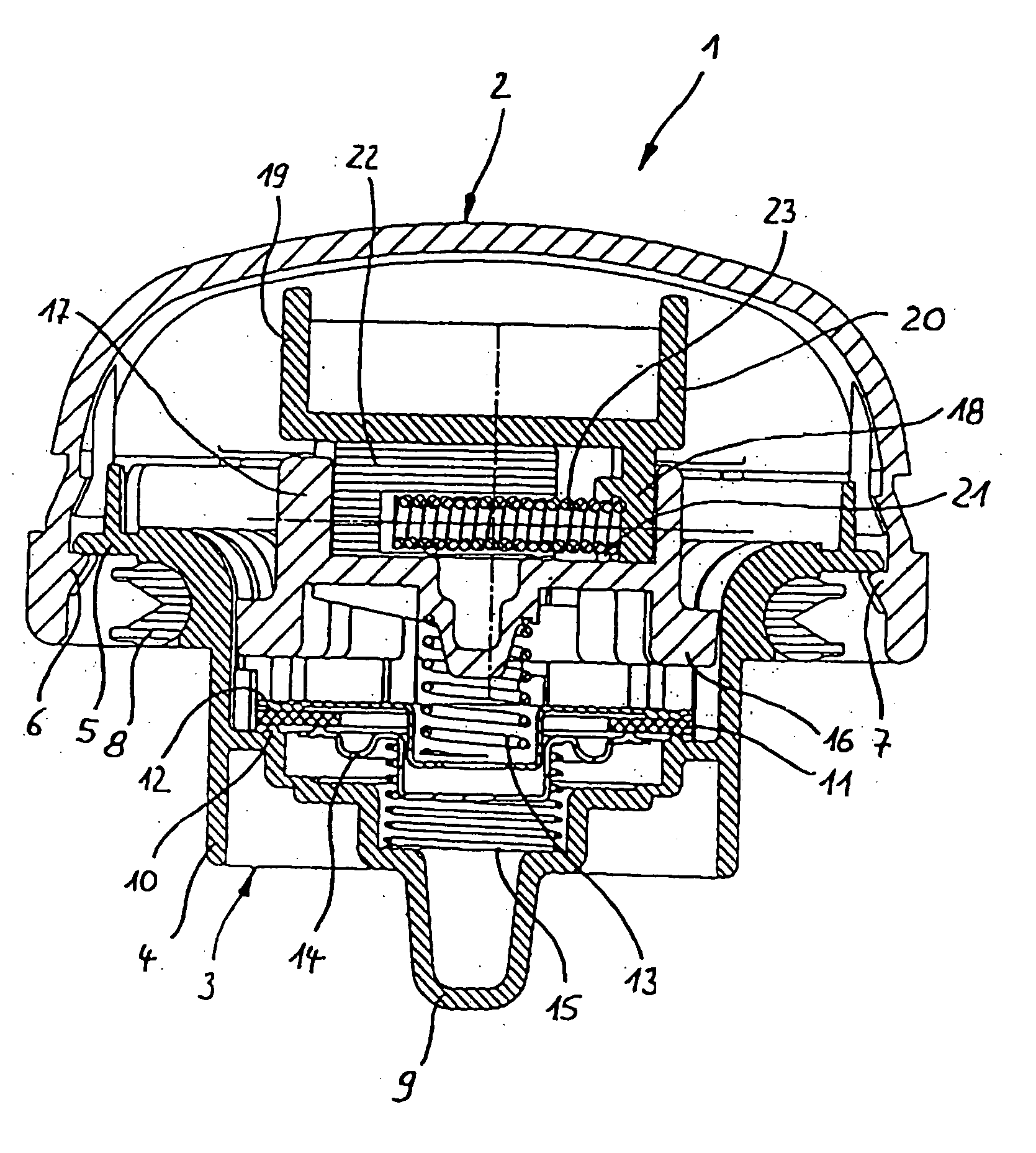
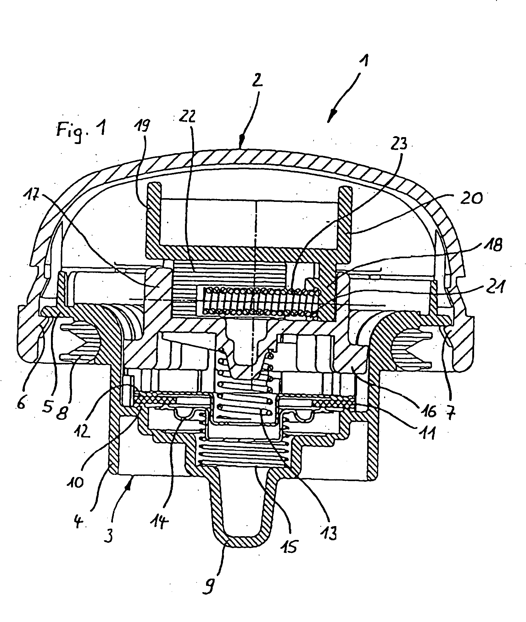
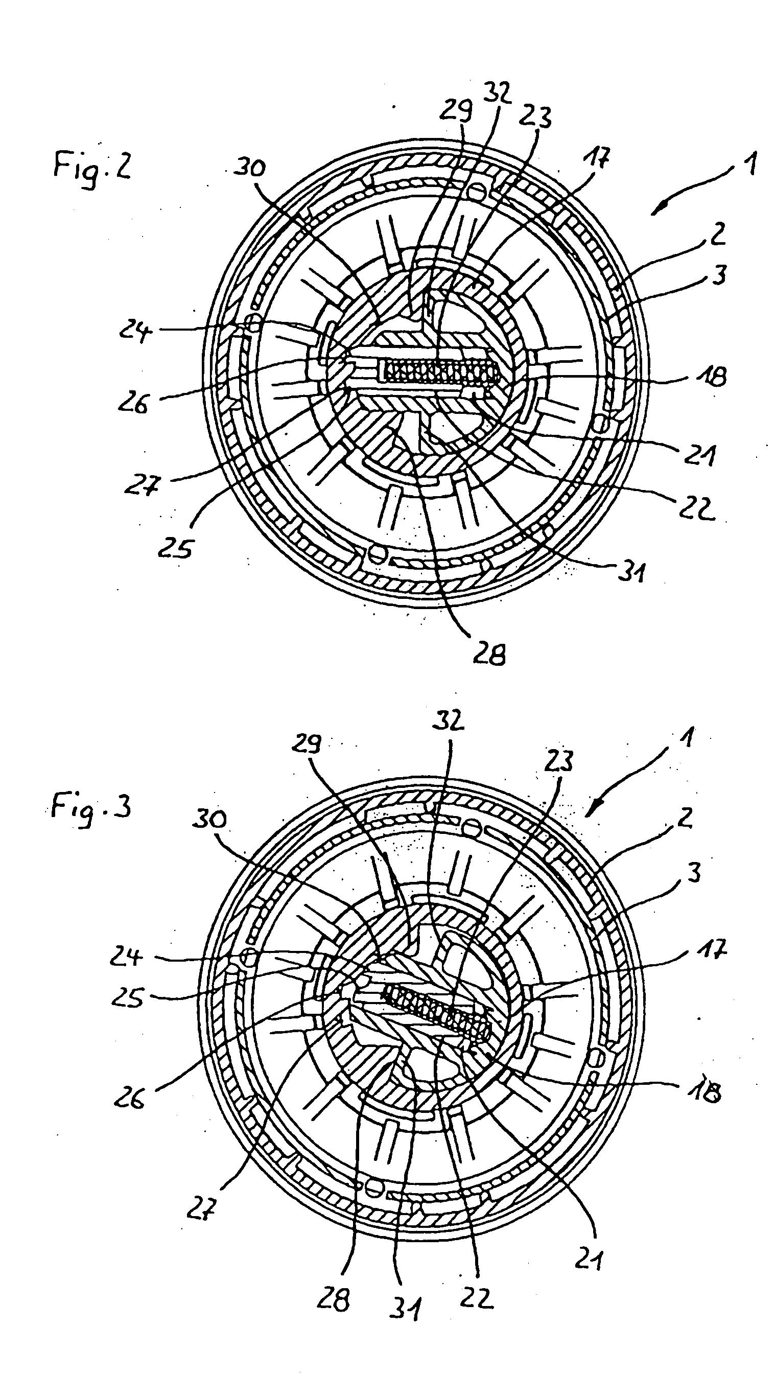
[0019] Tank cap 1 depicted in the Figures has a hat-shaped handle part 2 whose external shape is such that a flange projecting upward, at which tank cap 1 can be gripped, is formed. Handle part 2 is slipped over an engagement part 3 that comprises an engagement segment 4. Engagement segment 4 is provided on the outer side with engagement elements (not depicted here in detail), e.g. a thread, with which tank cap 1 can be brought into engagement with a corresponding thread in a tank neck. Engagement segment 4 transitions upward into a collar 5, horizontally bent over radially outward, beneath which handle part 2 is fitted by means of snap projections 6, 7. A sealing ring 8 surrounds the transition between engagement segment 4 and collar 5, and provides sealing with respect to the neck.

[0020] Engagement segment 4 comprises internally a support shell 9 that constitutes a valve seat ring 10. Support shell 9 has openings (not depicted here in detail) through which a connection is made t...


PUM


Abstract

A cap, in particular a tank cap, has a handle part for manipulating the cap upon screwing into and out of a neck, and has an engagement part for engagement of the cap in the neck. The handle part and engagement part are connected via a detent device that is embodied in such a way that in the screwing-in direction, after a detent resistance is overcome it allows the handle part to continue rotating out of a detent position relative to the engagement part with decreased rotation resistance. The detent device comprises only a single detent position; and a stop is provided for limiting the rotation angle of the handle part after the detent resistance is overcome.

Description

CROSS-REFERENCE TO RELATED APPLICATIONS AND CLAIM TO PRIORITY [0001] This application claims the benefit of utility model application number 203 13 900.3, filed Sep. 4, 2003, in the Federal Republic of Germany, the disclosure of which is incorporated herein by reference and priority to which is claimed under 35 U.S.C. § 119. FIELD OF THE INVENTION [0002] The invention concerns a cap, in particular a tank cap, having a handle part for manipulating the cap upon screwing into and out of a neck, and having an engagement part for engagement of the cap in the neck, the handle part and engagement part being connected via a detent device that is embodied in such a way that in the screwing-in direction, after a detent resistance is overcome it allows the handle part to continue rotating out of a detent position relative to the engagement part with decreased rotation resistance. BACKGROUND OF THE INVENTION [0003] For closing off a tank neck, tank caps are known in the existing art that compri...

Claims


Application Information

Patent Timeline
IPC IPC(8): B60K15/04
CPCB60K2015/0451B60K15/0406Y10S220/33
Inventor SCHERRER, KONRED H.
Owner TESMA EUROPA
Why Eureka
Try Eureka