
Control valve structure of plastic faucet

Inactive Publication Date: 2015-05-21
WU GARY
View PDF2 Cites 3 Cited by
  • Summary
  • Abstract
  • Description
  • Claims
  • Application Information

AI Technical Summary

Benefits of technology

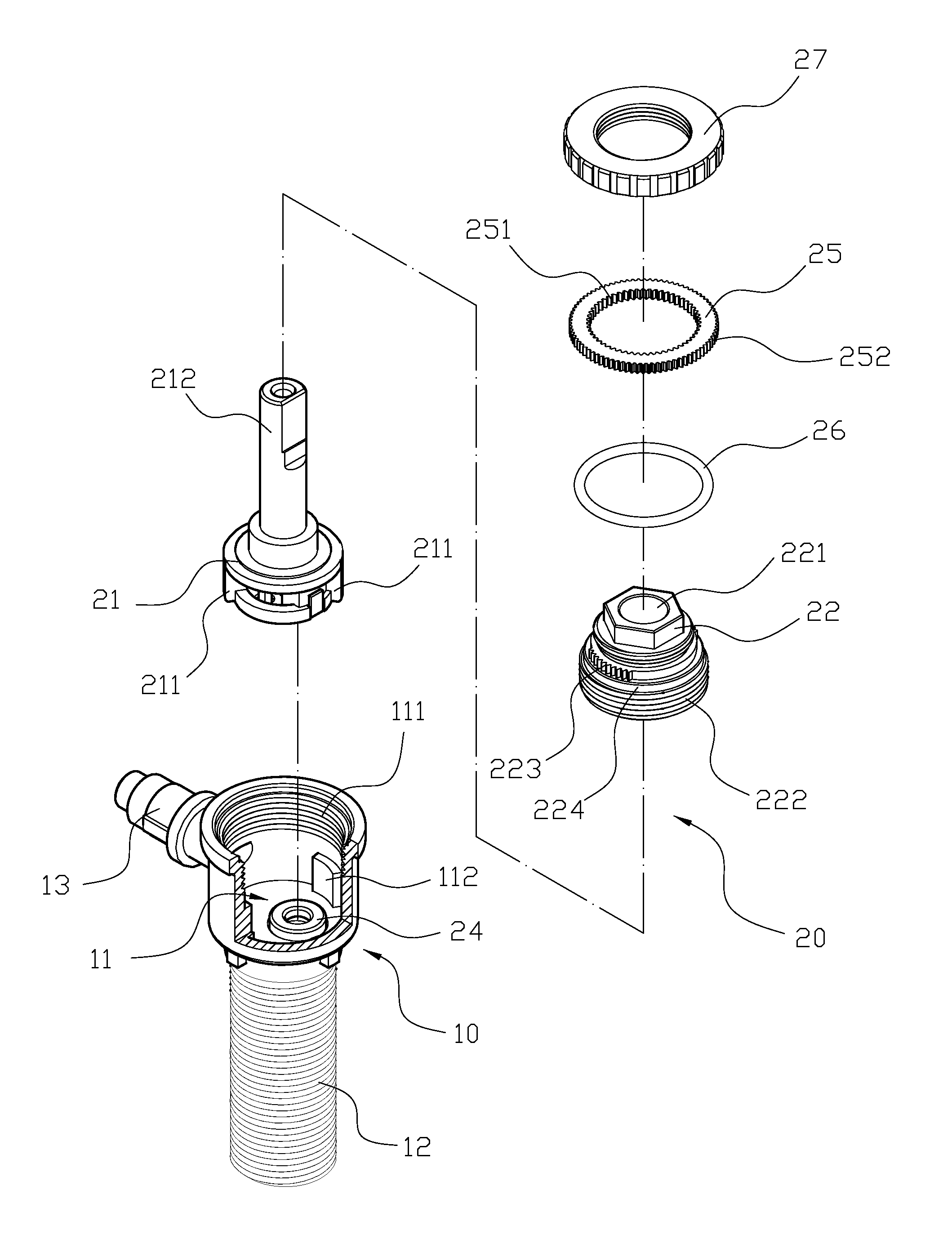
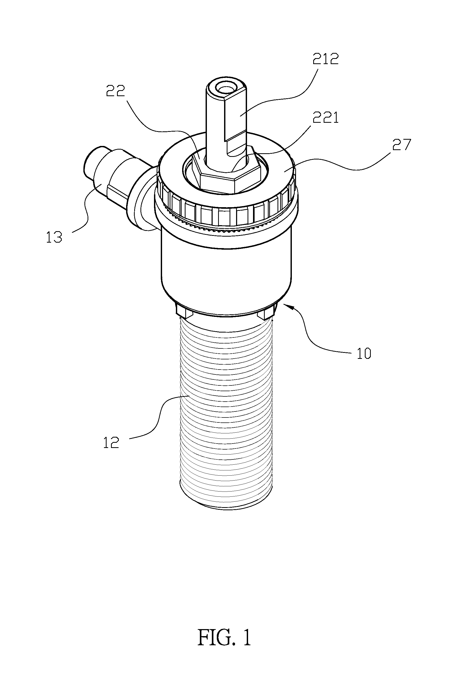
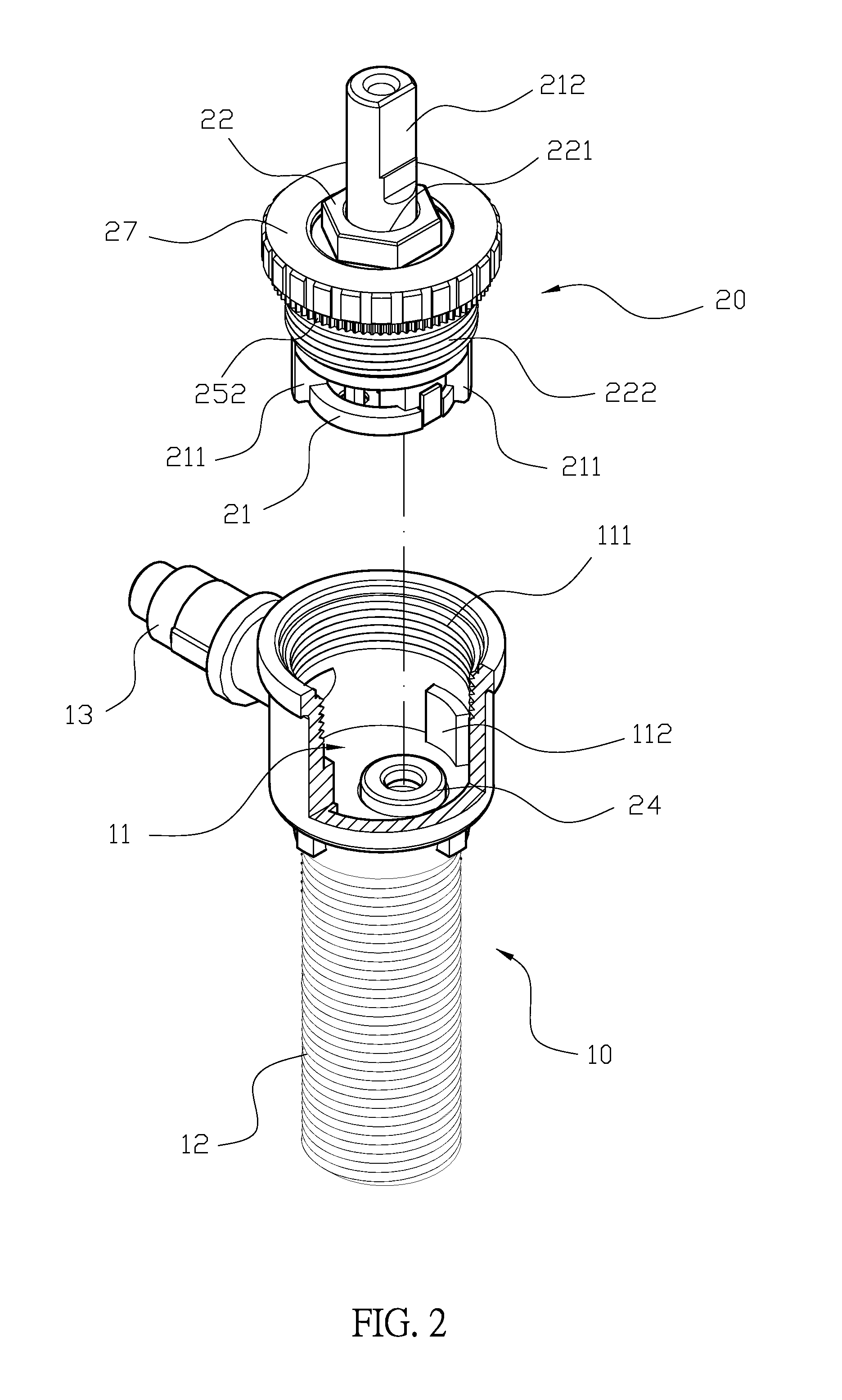
The present invention provides a plastic control valve with improved stability in boreal regions. The valve has inner threads in its receiving space that securely engage with the outer threads of the valve cover, preventing the cover from falling off due to water pressure. The valve also has a stopping block that restricts the rotation angle of the valve body to achieve water control, without using the valve cover to engage its outer threads. The valve cover has a teeth ring with inner and outer teeth sections that securely position the cover and prevent it from falling off.

Problems solved by technology

Therefore, it is apparent that the control valve A cannot be used in the boreal regions with low temperature.
The control valve disclosed above is disadvantageous because when the outer surface of the faucet is in the boreal regions with low temperature, the nut would be retracted due to low temperature.
Also, hot water flowing inside the tube body would cause thermal expansion of the stopping unit to reduce the gap between the stopping unit and the nut, so the stopping unit may break the nut to cause leakage.
Furthermore, rotation of the handle may collide and damage the stopping unit, so the stopping unit cannot effectively generate the restricting effect.

Method used


Image

  • Control valve structure of plastic faucet
  • Control valve structure of plastic faucet
  • Control valve structure of plastic faucet

Examples


Embodiment Construction

[0020]The detailed description set forth below is intended as a description of the presently exemplary device provided in accordance with aspects of the present invention and is not intended to represent the only forms in which the present invention may be prepared or utilized. It is to be understood, rather, that the same or equivalent functions and components may be accomplished by different embodiments that are also intended to be encompassed within the spirit and scope of the invention.

[0021]Unless defined otherwise, all technical and scientific terms used herein have the same meaning as commonly understood to one of ordinary skill in the art to which this invention belongs. Although any methods, devices and materials similar or equivalent to those described can be used in the practice or testing of the invention, the exemplary methods, devices and materials are now described.

[0022]All publications mentioned are incorporated by reference for the purpose of describing and disclos...


PUM


Abstract

A plastic control valve is connected to a plastic tube body to control water output. The tube body has a receiving space, inner portion of the receiving space has inner threads, and at least one stopping block is protrudingly formed at a bottom surface of the receiving space, wherein said control valve has a valve body, a valve cover, and at least a wedging block formed at an outer portion of the valve body, wherein the valve body is disposed into the receiving space of the valve shell, and the wedging block and stopping block are rotatably secured with each other, wherein the valve cover has outer threads formed at an outer surface thereof to engage with the inner threads of the valve shell to eliminate squeeze between the tube body and valve cover due to thermal expansion and retraction to further increase the stability of the control valve.

Description

FIELD OF THE INVENTION[0001]The present invention relates to a faucet structure, and more particularly to a control valve structure of a plastic faucet used in boreal regions.BACKGROUND OF THE INVENTION[0002]A conventional plastic control valve structure in a faucet is shown in FIGS. 10 and 11. The control valve A has a valve body 40, a valve base 50, a stop member 60 and a cap 70. The entire control valve A is made by plastic, wherein the valve body 40 has a valve space 43 between a water inlet tube 41 and a water outlet tube 42, and two recessed slots 431 are formed at the inner edge of the valve space 43. Also, outer threads 432 are formed outside the valve space 43 and the valve base 50 is disposed in the valve space 43 of the valve body 40, and a spring 51 and a sleeve body 52 are disposed at the water inlet end 41. A shaft hole 61 is formed at the center of the stop member 60, and two protruding blocks 62 are protrudingly formed at the outer surface of the stop member 60. The ...

Claims


Application Information

Patent Timeline
IPC IPC(8): F16K27/04F16K27/12F16K3/24
CPCF16K27/041F16K27/12F16K3/243F16K3/04F16K19/006F16K27/045
Inventor WU, GARY
Owner WU GARY
Learn More