
Faucet Mounting Sleeve

Active Publication Date: 2009-01-08
WCM IND INC
View PDF57 Cites 19 Cited by
  • Summary
  • Abstract
  • Description
  • Claims
  • Application Information

AI Technical Summary

Benefits of technology

[0007]It is one aspect of the present invention to provide a mounting box that supports a faucet assembly. More specifically, embodiments of the present invention employ a mounting sleeve that is associated with a fluid delivery tube that terminates at a faucet. The mounting sleeve is interconnected to at least one supporting bracket. The bracket is adapted for interconnection to an interior building surface, which increases the stability of the interconnection of the faucet assembly to the dwelling. The mounting sleeve is adapted to secure the fluid delivery tube and to provide a location for interconnection of the faucet. Embodiments of the present invention employ a mounting sleeve that is selectively adjustable such that a flange of the faucet, which traditionally is used to secure the faucet to an exterior building surface, may be placed generally adjacent to the outer surface of the dwelling and not interconnected directly to it.
[0008]Another aspect of the present invention is to provide a system for mounting a wall faucet to a building that increases the stability of the interconnection of the faucet to the building. More specifically, as opposed to prior art methods of interconnecting a wall faucet assembly to a dwelling, embodiments of the present invention employ one or more brackets that are interconnected to an interior (or exterior) building surface. For example, the brackets of the invention may be interconnected to the inside or outside of any building member, such as 2×4 studs, sill plates, a concrete basement wall, a foundation member, headers, sheathing, etc. Interconnecting the brackets to a structural element improves the structurally stability of the faucet assembly. That is, as opposed to prior art systems, which interconnect a the faucet flange directly to an exterior building surface, the mounting sleeve employed in various embodiments of the present invention is held within the brackets, thus supplying a sufficient support to the faucet assembly. In such a manner the above-identified issues related to interconnecting a faucet to mortar, rock, stone, bricks, stucco, etc., are reduced if not eliminated. The method and associated apparatus of the present invention for securing a tube within mounting sleeve, which is then interconnected to a rigidly interconnected bracket, is superior over prior art methods and system of interconnection.
[0009]It is another aspect of the present invention to provide a mounting system and methods that allow for robust installation. More specifically, embodiments of the present invention may be installed prior to or after the siding or other exterior building surface is installed. The brackets that secure the mounting sleeve may be installed by the framers, siding installers or plumbers. Guess work as to the location of the faucet is thus reduced. This aspect of the present invention is made possible by the fact that the faucet does not need to be initially installed in order to install the bracket and to locate the mounting sleeve. After installation of the mounting sleeve, the mounting sleeve may be removed from the bracket and associated with the tube of the faucet, for example.

Problems solved by technology

One skilled in the art will appreciate that it is difficult to interconnect the flange of the faucet to non-continuous building surfaces.
Long screws, however, are unstable and provide little support to the faucet.
These forces may be associated with weakening of the interconnection of the faucet to the dwelling and may cause the faucet to dislocate from the exterior building surface.
Thus, faucet assemblies that are interconnected to such non-continuous and uneven building surfaces are often not very structurally stable.
If the faucet assembly is unstable it could also separate from the fluid supply line, thereby causing water / mold damage.
This additional work increases the time and cost of installation.
One drawback of the PerfectSett device is that it does not provide selective adjustments and only accommodates exterior building surfaces of a set thickness.

Method used


Image

  • Faucet Mounting Sleeve
  • Faucet Mounting Sleeve
  • Faucet Mounting Sleeve

Examples


Embodiment Construction

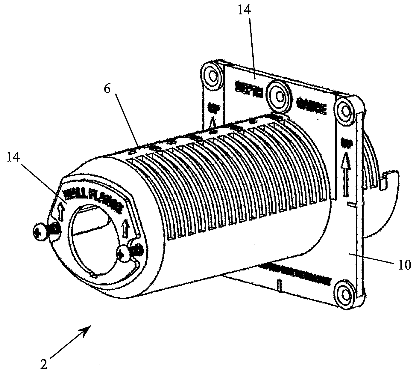
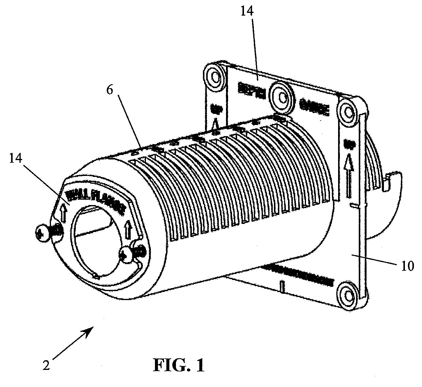
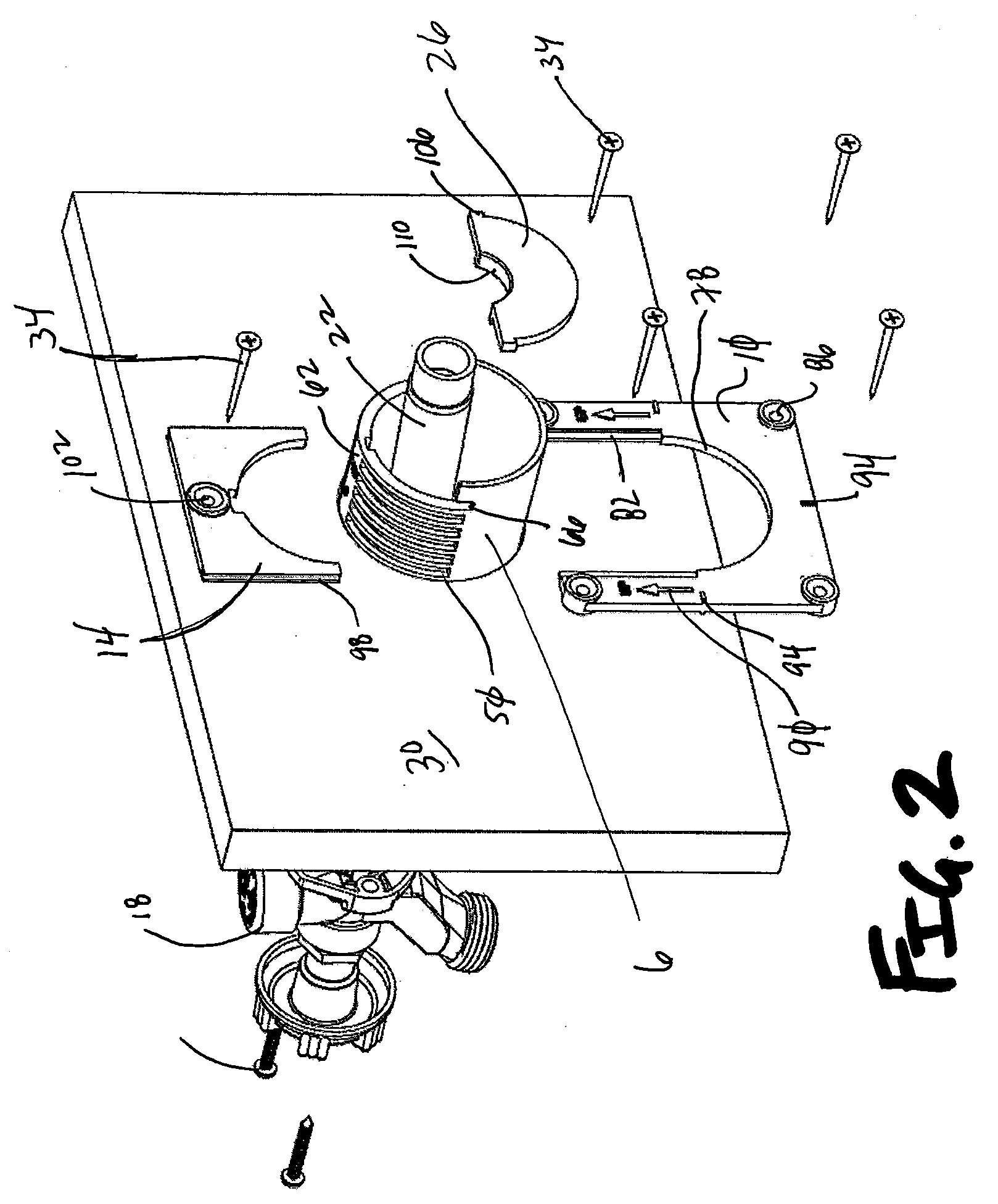
[0055]Referring now to FIGS. 1-33, a faucet mounting assembly 2 of one embodiment of the present invention is provided that includes a mounting sleeve 6 that is selectively interconnected to a bottom bracket 10. The mounting sleeve 6 is held in place relative to the bottom bracket 10 by a top bracket 14. In operation, a faucet 18 and associated tube 22 are designed to interface with the mounting sleeve 6, thereby securing the faucet 18 to a dwelling. A tube rest 26 is interconnected to a rear portion of the mounting sleeve 6 that supports and angles the tube 22 such that drainage is facilitated which prevents freezing. Embodiments of the present invention are designed to interconnect to an interior wall 30 of a building via a plurality of fasteners 34, thus creating a stable interconnection between the faucet assembly (i.e., the faucet 18 and tube 22) over the interconnection schemes employed by the prior art. In operation, the bottom bracket 10 is interconnected to the wall 30 and ...


PUM


Abstract

A system for mounting a faucet to the exterior portion of a dwelling is provided. A mounting sleeve is employed that is associated with a tube that is interconnected to the faucet that is generally positioned outside of a dwelling. The tube is rigidly interconnected to a mounting sleeve that is supported by at least one bracket that allows for selective adjustments. That is, the mounting sleeve may be selectively offset from the interior surface of the dwelling, thereby accommodating exterior building surfaces with irregular shapes such as stone, brick, mortar, stucco, etc. The mounting system provides additional rigidity to the faucet / dwelling interconnection.

Description

[0001]This application claims the benefit of U.S. Provisional Patent Application Ser. No. 60 / 947,902, filed Jul. 3, 2007, the entire disclosure of which is incorporated by reference herein.FIELD OF THE INVENTION[0002]Embodiments of the present invention are generally related to devices for securing faucets, or other fluid delivery devices, to a building surface. More specifically, a mounting assembly is used in conjunction with securing a faucet to an uneven exterior surface of a dwelling.BACKGROUND OF THE INVENTION[0003]Wall faucets are very common and often found mounted to the exterior of a dwelling to be used for supplying water outside of the dwelling. Wall faucets include a faucet assembly with a flange that is designed to interconnect to an exterior surface of a dwelling. The wall faucet assembly also includes a tube that is in fluidic communication with the water source of the dwelling. Traditionally, the flanges have been mounted to an exterior surface, i.e. siding of the d...

Claims


Application Information

Patent Timeline
IPC IPC(8): F16L41/16
CPCE04G15/061F16L5/00F16L3/00Y10T137/8275Y10T137/698Y10T137/6014Y10T137/6977
Inventor BALL, WILLIAM T.
Owner WCM IND INC
Learn More