Plug-in connection having shielding

Active Publication Date: 2012-08-09
ERNI PRODION GMBH
View PDF9 Cites 20 Cited by
  • Summary
  • Abstract
  • Description
  • Claims
  • Application Information

AI Technical Summary

Benefits of technology

[0018]An especially advantageous configuration provides that reinforcing ribs are arranged in the male multipoint connector housing in the region of the respectively offset contact groups in which a cavity is formed. As a result, such reinforcing ribs are respectively provi

Problems solved by technology

This arrangement in conjunction with the L-shaped shielding elements that do not completely shield the signal contacts and their arrangement do not allow any disturbance-free signal transmission in the very high frequency range.
Such an arrangement does not easily enable a densely packed arrangement of the signal and shielding contact elements.
Moreover, the signal behavior is not optimal in such a connector.
As a result of the straight arrangement of the contact group

Method used


Image

  • Plug-in connection having shielding
  • Plug-in connection having shielding
  • Plug-in connection having shielding

Examples


Example

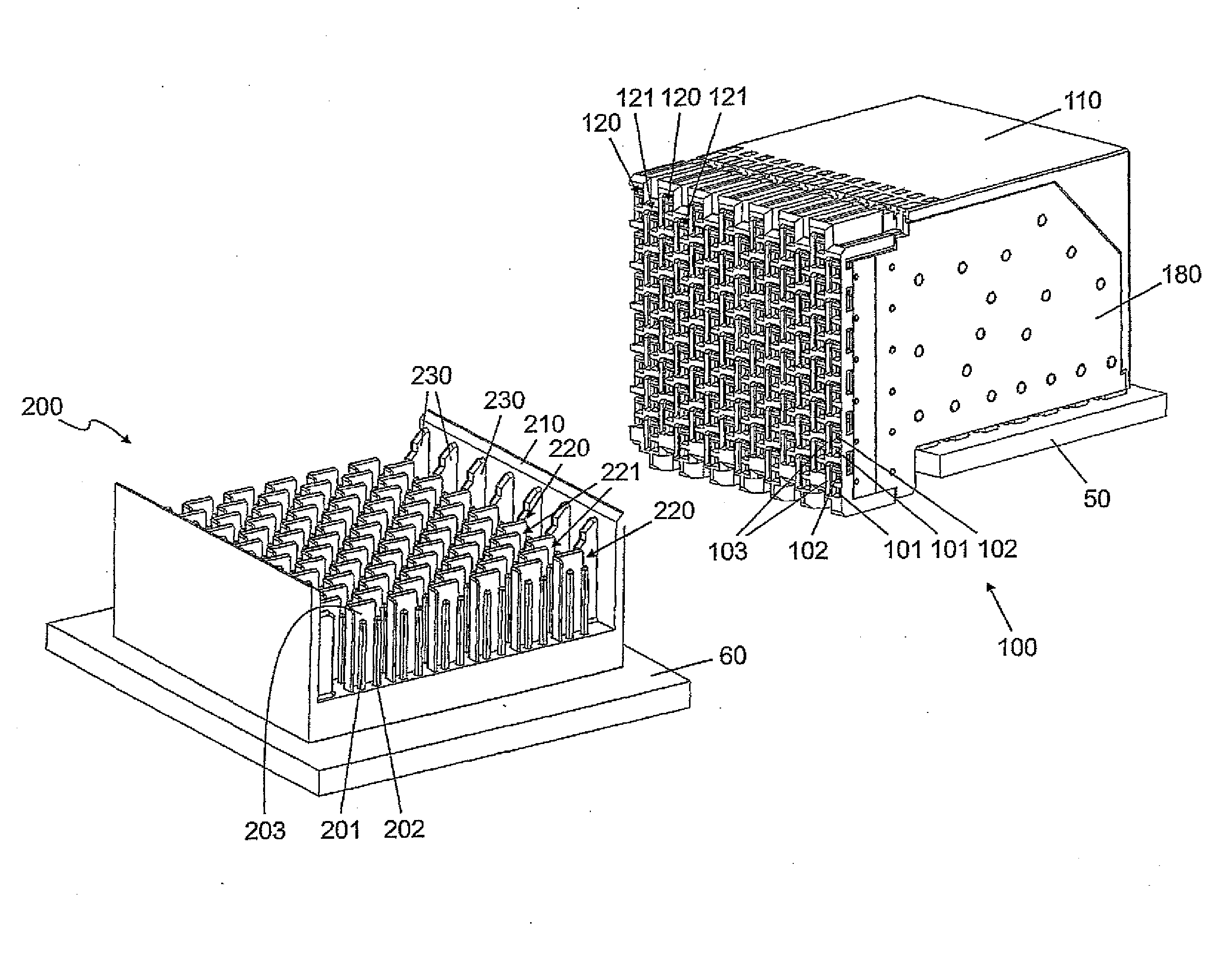
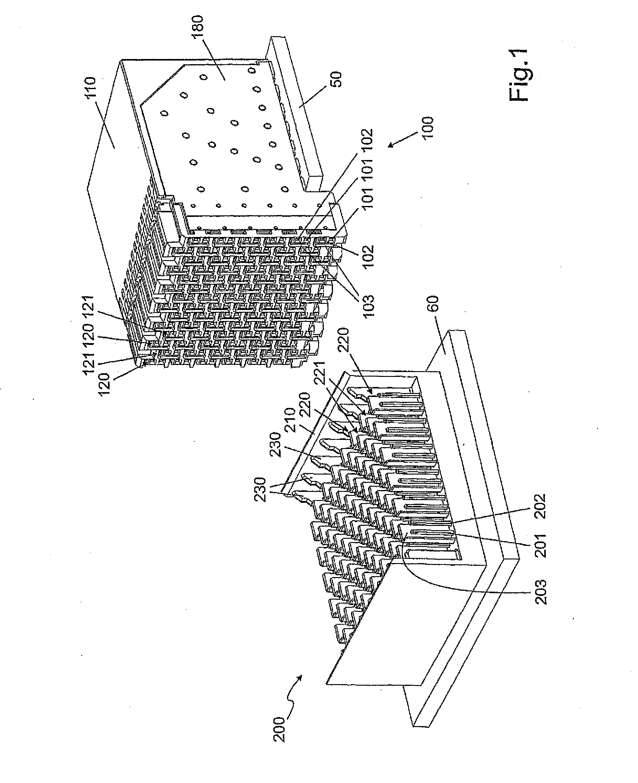
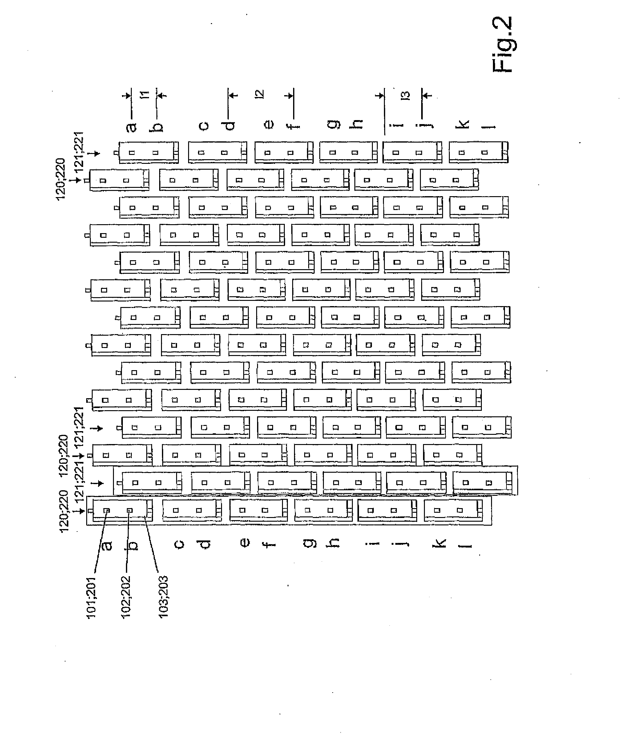
[0032]FIG. 1 shows a female multipoint connector 100 in the right half of the drawing, which female multipoint connector is fixed to and in contact with a circuit board 50 by means of soldered or pressed connections for example. The female multipoint connector comprises a plurality of contact group columns 120 on its front side, which columns are respectively arranged in parallel with respect to each other. Every contact group column 120 comprises a plurality of differential contact pairs 101, 102 which are arranged above one another and which are respectively enclosed by an L-shaped shielding plate 103. Two differential contacts 101, 102 and the associated shielding plate 103 respectively form one contact group. The plug therefore consists of a plurality of contact group columns and contact group rows, with the contact group rows being characterized in such a way that adjacent contact groups in an adjacent contact group column are respectively arranged in an offset manner by a pred...


PUM


Abstract

The invention relates to a plug-in connection having shielding, in particular a multi-pin, multi-row plug-in connection comprising a male multipoint connector and a female multipoint connector, the plug-in connection comprising signal contacts, which are arranged in a contact pattern of differential pairs and which form a contact group together with an L-shaped shielding element that surrounds the signal contacts, the contact groups being arranged in rows and columns and adjacent contact groups in adjacent columns being offset from each other by a specifiable length dimension in the longitudinal direction of the columns, the plug-in connection being characterized in that the specified length dimension corresponds to approximately half the distance of two adjacent contact groups in a column.

Description

[0001]The invention relates to a plug-in connection with shielding, especially a multi-pin, multi-row plug-in connection consisting of a male multipoint connector and a female multipoint connector, which respectively comprise signal contacts which are arranged in contact patterns of differential pairs and which form a contact group together with an L-shaped shielding element that surrounds said signal contacts, with the contact groups being arranged in rows and columns and adjacent contact groups in adjacent columns being offset from each other by a predeterminable length dimension in the longitudinal direction of the columns.DESCRIPTION OF THE PRIOR ART[0002]A plug-in connection of this kind is disclosed by DE 603 16 145 T2 for example. In this plug-in connection, adjacent contact groups in adjacent columns are respectively arranged in an offset manner with respect to each other by a predeterminable length dimension in the longitudinal direction of the columns. The signal contacts ...

Claims


Application Information

Patent Timeline
IPC IPC(8): H01R13/648
CPCH01R12/585H01R13/514H01R12/716H01R23/688H01R13/6587H01R12/724H01R13/6471H01R12/71H01R12/712H01R12/714H01R13/518H01R13/658H01R13/6581H01R13/6582H01R13/6583
Inventor LAPPOEHN, JUERGEN
Owner ERNI PRODION GMBH
Why Eureka
Try Eureka