Twist-grip bicycle shifter

a shifter and bicycle technology, applied in the direction of cycle equipment, mechanical control devices, instruments, etc., can solve the problems of actuating elements, housing elements, dangerous falls, and high cost and time-consuming

Inactive Publication Date: 2008-07-22
SRAM +1
View PDF11 Cites 4 Cited by
  • Summary
  • Abstract
  • Description
  • Claims
  • Application Information

AI Technical Summary

Benefits of technology

[0005]The object of the present invention is therefore to provide a twistshifter in which the securing of the actuating element to the housing element occurs automatically at the time the actuating element is assembled to the housing element and requires no additional parts such as locking elements required to secure the actuating element to the housing element in an axial direction.
[0006]The twistshifter of the present invention has a housing element which may be fixed to the handlebar. The housing element may form a ring. The twistshifter also includes an actuating element which may be rotated about the axis of the handlebar. The angle of rotation of the actuating element is limited. The actuating element may be fixed axially to the housing element by using a locking device having latching elements. A first latching element of the locking device is joined to the housing element or is situated on the housing element. In contrast to the twistshifters of the prior art, a second latching element, does not form an additional part but rather is situated directly on the actuating element itself. This eliminates the need to provide an additional locking part on which it was necessary to arrange the second latching element of complementary shape to the first latching element. The elimination of the additional locking part reduces the cost of tooling, production and assembly. Moreover, the problem of losing or forgetting the locking part during assembly which may adversely affect riding safety is also eliminated.
[0007]According to one embodiment of the present invention, both the first and second latching elements are arranged on a circumference of the twistshifter near the handlebar. Arranging the latching elements of the locking device near the handlebar results in increased inherent stiffness of the latching elements in an axial direction in particular, as a result of which the considerable hand and arm forces occurring during cycling may be transferred more reliably to the bicycle handlebar without the danger of axially decoupling the actuating element under use. The arrangement of the latching elements of the locking device on a circumference of the twistshifter near the handlebar surface ensures that once joined, the actuating element may only be detached from the housing element when the twistshifter is removed from the handlebar.

Problems solved by technology

An actuating element of a twistshifter that is not or inadequately secured against axial movements might otherwise slip off from the end of the handlebar as a consequence of the arm forces transferred to the handlebar via the handlebar grips during cycling, potentially causing dangerous falls.
The manufacture and installation of the locking element, the housing element, and actuating element of the twistshifter and in addition to the necessary complementary-shaped companion parts to be joined to the housing element, is expensive and time-consuming.
Moreover, the tools for manufacturing the parts are complex and also expensive.
In addition, the discrete locking element may be lost or forgotten during assembly or installation of the twistshifter, resulting in a temporarily functional twistshifter, but one under risk of having the actuating element slide off the handlebar end during use.

Method used


Image

  • Twist-grip bicycle shifter
  • Twist-grip bicycle shifter
  • Twist-grip bicycle shifter

Examples


Embodiment Construction

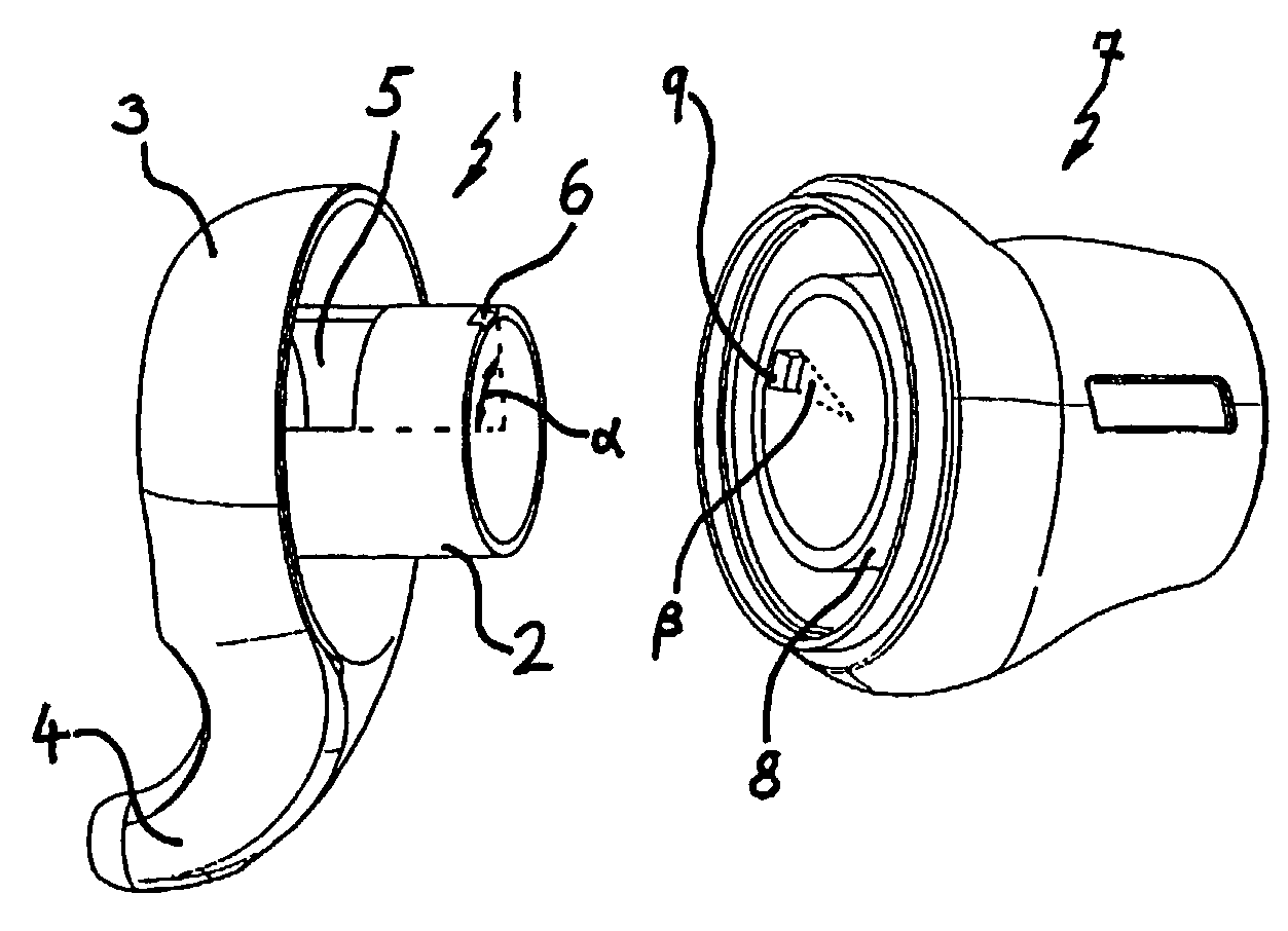
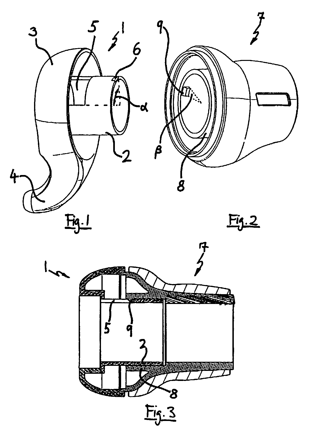
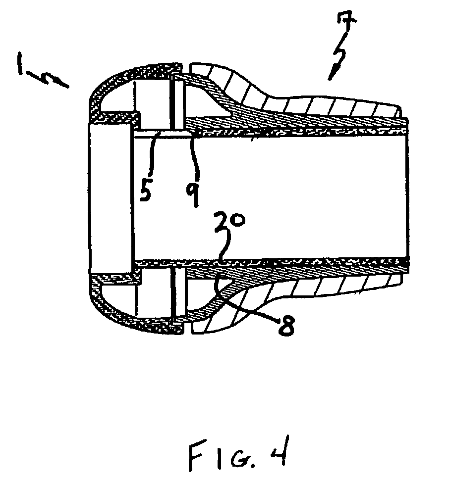
[0019]FIG. 1 shows a housing element of a twistshifter. The housing element 1 includes a mandrel 2 designed as a cylinder, a housing cover 3 and a housing extension 4 for accommodating a cable (not shown). An inside diameter of mandrel 2 is slightly larger than an outer diameter of a handlebar (not shown) so that the housing element 1 may be slipped on an end of the handlebar. The housing element 1 may be fixedly joined to the handlebar by a screw device or clamping device (not shown). In addition, the housing element 1 of the twistshifter includes a cutout recess 5, which forms one of the two latching elements of a locking device to join an actuating element 7 to the housing element 1 of the twistshifter. Moreover, the housing element 1 may include a chamfer 6 to lift a latching element 9 of the actuating element 7 onto the mandrel 2 upon assembly.

[0020]Referring now to FIG. 2, the actuating element 7 has a cylindrical interior 8. The inside diameter of the actuating element 7 corr...


PUM


Abstract

A twistshifter mounted about a handlebar. The twist-shifter includes a housing element which may be fixed to the handlebar and an actuating element which may be rotated about the axis of the handlebar tube a predetermined angle. The actuating element may be fixed axially to the housing element by a locking device having interlocking first and second latching elements. The first latching element is arranged on the housing element. The second latching element that is complementary in shape to the first latching element is arranged on the actuating element.

Description

BACKGROUND OF INVENTION[0001]This invention relates to twist-grip shifters for bicycles in particular a twist-grip shifter having an integrated locking device that connects a housing element and an actuating element of the twist-grip shifter.[0002]Twistshifters are widely used in bicycles of nearly all types and quality classes. The object of such twistshifters is to make it possible for the cyclist to manually select and monitor the desired gear ratio of the bicycle transmission manually in a simple, safe and ergonomic manner. Twistshifters may be used to actuate internal gear hubs or derailleurs. Twistshifters usually include a housing element mounted to the handlebar near the end of the handlebar. Such shifters also include an actuating element that is rotatable about the axis of the handlebar. Both the housing element and the actuating element are generally mounted about the handlebar in the form of a ring. The actuating element is generally provided with a non-slip outer surfac...

Claims


Application Information

Patent Timeline
Patent Type & Authority Patents(United States)
IPC IPC(8): F16C1/12B62M25/04B62K23/04
CPCB62K23/04B62M25/04Y10T74/2042Y10T74/20474
Inventor BLASCHKE, GEORG K.
Owner SRAM
Why Eureka
Try Eureka